Electrically controlled manual locking mechanism of sliding-plug door and sliding-plug door applying electrically controlled manual locking mechanism

A manual lock and electric control technology, which is applied in the field of sliding doors and electric control manual locking mechanisms of sliding doors, can solve the problems that the motor cannot work, the electric sliding doors cannot work normally, and cannot be unlocked and locked. To achieve the effect of stable locking function

Active Publication Date: 2018-05-29
南京启越机电设备有限公司
View PDF11 Cites 9 Cited by
  • Summary
  • Abstract
  • Description
  • Claims
  • Application Information

AI Technical Summary

Problems solved by technology

[0004] The opening and locking of the above-mentioned electric sliding door locking and unlocking mechanism depends on the rotation of the motor, but the motor cannot work when the motor is powered off. Just cause can't unlock and lock, make electric sliding door can't work normally, therefore, be badly in need of a kind of sliding door locking mechanism that also can normally open and close of door lock under power-off situation

Method used


Image

  • Electrically controlled manual locking mechanism of sliding-plug door and sliding-plug door applying electrically controlled manual locking mechanism
  • Electrically controlled manual locking mechanism of sliding-plug door and sliding-plug door applying electrically controlled manual locking mechanism
  • Electrically controlled manual locking mechanism of sliding-plug door and sliding-plug door applying electrically controlled manual locking mechanism

Examples


Embodiment 1

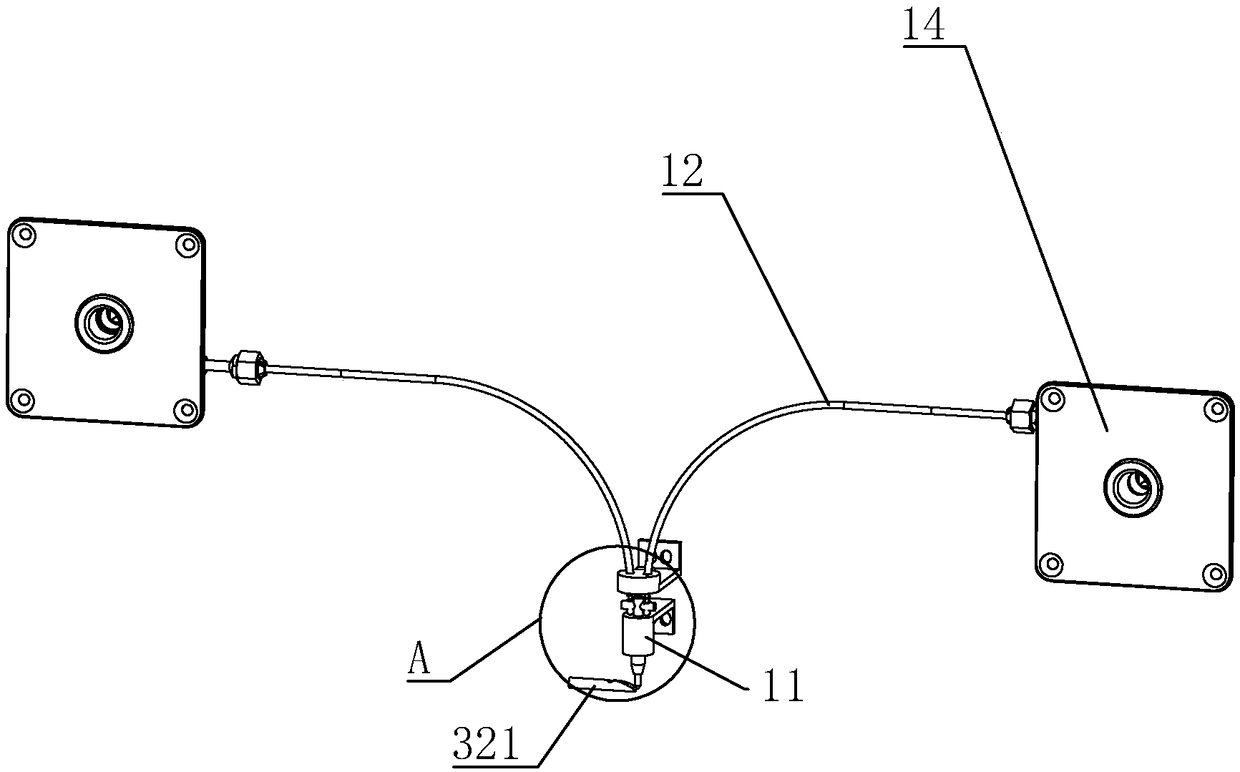
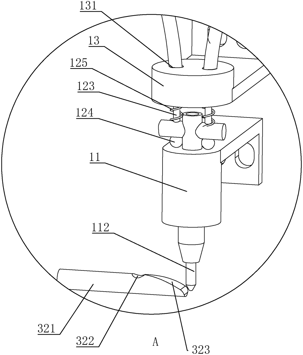
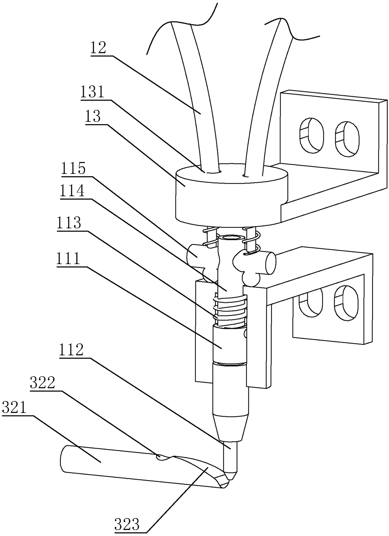
[0054] Embodiment 1: An electronically controlled manual locking mechanism for a plug door, such as figure 1 , 3 shown, including mounting on the mast 1 (as Figure 9 shown) on the electromagnet 11 and with the plug door 7 (such as Figure 9 As shown) the lock tongue 321 that acts together to control the moving state of the plug door 7 is fixedly connected to the armature 111 in the electromagnet 11 with a cylindrical locking rod 112, and the locking rod 112 passes through the bottom of the electromagnet 11 , a compression spring 113 is arranged inside the electromagnet 11, one end of the compression spring 113 is fixedly connected with the end of the armature 111 away from the locking rod 112, and the other end is fixedly connected with the inside of the electromagnet 11, and at the position where the armature 111 is away from the locking rod 112 One end is provided with a cylindrical connecting rod 114, the connecting rod 114 passes through the electromagnet 11 and is conn...

Embodiment 2

[0063] Embodiment 2: An electronically controlled manual locking mechanism for a plug door, the difference from Embodiment 1 is that, as Figure 5As shown, the connecting rod 114 is provided with a stroke hole 116 through which the driving rod 115 passes, and the stroke hole 116 extends along the axis of the connecting rod 114 . When the locking rod 112 was inserted into the locking hole 322 to limit the movement of the dead bolt 321, the driving rod 115 just collided with the side hole wall of the stroke hole 116 away from the armature 111; When the tongue 321 is unlocked, the driving rod 115 just or does not interfere with the side hole wall of the stroke hole 116 near the armature 111, that is, the stroke of the stroke hole 116 is greater than or equal to the depth of the locking rod 112 inserted into the locking hole 322.

[0064] Such as Figure 6 As shown, a fixed tube 15 is also arranged directly below the electromagnet 11 on the door frame 1, the axis of the fixed tub...

Embodiment 3

[0066] Embodiment 3: a kind of sliding door, such as Figure 7 , 8 As shown, it includes a driving wheel 21 installed on the door frame 1 , a driven wheel 22 and a motor 2 for driving the driving wheel 21 to rotate, and the driving wheel 21 and the driven wheel 22 are linked by a toothed belt 23 .

[0067] Such as Figure 8 As shown, a linear guide rail 3 with a U-shaped cross-section is fixedly connected to the door frame 1. The linear guide rail 3 is located below the toothed belt 23 and is parallel to the toothed belt 23. A slider is slidably connected to the linear guide rail 3. 31.

[0068] Such as Figure 8 and 10 As shown, a connecting plate 32 is fixedly connected to the side of the slider 31 away from the linear guide rail 3, and is fixedly connected to the toothed belt 23 through the belt clamp 231 above the connecting plate 32. On the side of the connecting plate 32 away from the linear guide rail 3 A self-lubricating radial joint bearing-411 is fixedly connect...


PUM


Abstract

The invention discloses an electrically controlled manual locking mechanism of a sliding-plug door and the sliding-plug door applying the electrically controlled manual locking mechanism, and belongsto the technical field of electric door equipment. According to the electrically controlled manual locking mechanism of the sliding-plug door, opening and closing of the sliding-plug door can be stillachieved in the case of power failure. According to the technical scheme of the electrically controlled manual locking mechanism, the electrically controlled manual locking mechanism of the sliding-plug door comprises an electromagnet arranged on a door frame and a locking dog moving together along with the sliding-plug door, one end of an armature in the electromagnet is fixedly connected with alocking rod, the locking rod extends out to the exterior of the electromagnet, and the electromagnet is internally provided with a first compression spring used for pushing the armature outwards; theend, away from the locking rod, of the armature is provided with a traction piece used for manually dragging the armature to move in the direction away from the locking rod; and the locking dog is provided with a locking hole for allowing the locking rod to be inserted into for locking, and the end, facing the locking rod, of the locking dog is provided with a wedge-shaped surface used for jacking the locking rod to the interior of the electromagnet.

Description

technical field [0001] The invention relates to electric door equipment technology, in particular to an electric-controlled manual locking mechanism for a plug door and a plug door using the mechanism. Background technique [0002] The so-called plug door mainly means that the door has two actions of plugging and pulling, that is, the door is closed by being inserted into the door of the car from the inside or outside of the car to make it closed and sealed; After that, it can slide inside or outside the car body. [0003] The Chinese patent with the publication number CN103046827A discloses a locking and unlocking mechanism for an electric plug door, which includes a locking and unlocking assembly and a motor swing rod drive assembly. The locking and unlocking assembly includes an unlocking swing rod, a left swing rod, a right swing rod, a pull rod and a joint bearing connection. The locking and unlocking component is connected with the motor swing rod drive component thr...

Claims


Application Information

Patent Timeline
Patent Type & Authority Applications(China)
IPC IPC(8): E05B81/90E05B81/08E05B81/14E05B85/22E05B79/20E05B83/40B61D19/02
CPCE05B79/20E05B81/08E05B81/14E05B81/90E05B83/363E05B83/40E05B85/22B61D19/005B61D19/02Y02T10/7072Y02T10/70Y02T90/14
Inventor 孙静国
Owner 南京启越机电设备有限公司
Why Eureka
Try Eureka