A water pump high-pressure pressurizing device

A technology of a pressurizing device and a pumping pump, which is applied to the components, pump components, pump control and other directions of the pumping device for elastic fluids, can solve the problems of high cost, high power consumption, and is not environmentally friendly, and achieves low cost, The effect of improving the utilization rate of water energy and simple structure

Active Publication Date: 2019-02-26
南通和信工程勘测设计院有限公司
View PDF5 Cites 0 Cited by
  • Summary
  • Abstract
  • Description
  • Claims
  • Application Information

AI Technical Summary

Problems solved by technology

[0002] The existing water pump provides the power source through the motor, and the motor drives the water-pressing mechanism inside the pump. The water-pressing mechanism quickly and briefly pushes the water in the pump to move forward to realize the pumping of the pump. For high-lift pumping, this method consumes power Big, expensive, and not environmentally friendly

Method used


Image

  • A water pump high-pressure pressurizing device
  • A water pump high-pressure pressurizing device
  • A water pump high-pressure pressurizing device

Examples


Embodiment 1

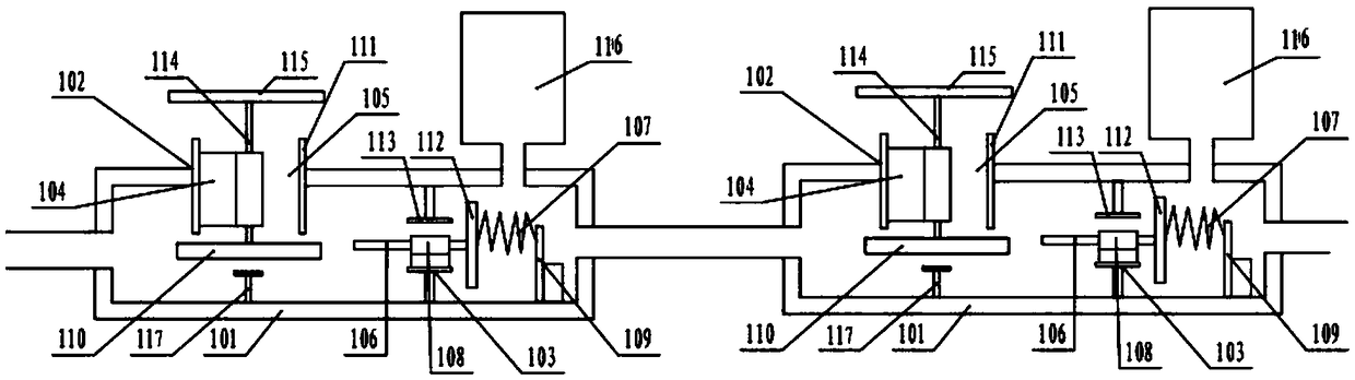
[0021] Embodiment 1: as Figure 1~Figure 8 As shown, a high-pressure pressurization device for a water pump includes at least two pressurization devices 1 connected in series, the water inlet of the first pressurization device 1 is connected to a high-level water source, and the water outlet is connected to the water inlet of the next-stage pressurization device 1 , the water inlet of the pressurizing device 1 adjacent to the previous stage is larger than the water inlet of the pressurizing device 1 of the subsequent stage.

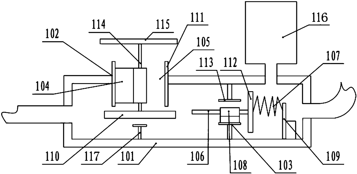
[0022] Preferably, the above-mentioned pressurizing device 1 includes a cavity 101, the side wall of the water inlet end of the cavity 101 is provided with a valve one 102, and the water outlet end is provided with a valve two 103, the valve one 102 includes a valve plate 110 and a valve cavity 111, the valve plate The upper end surface of a 110 is connected with a valve shaft 114, and the valve shaft 114 passes through the valve cavity 111 and is connect...

Embodiment 2

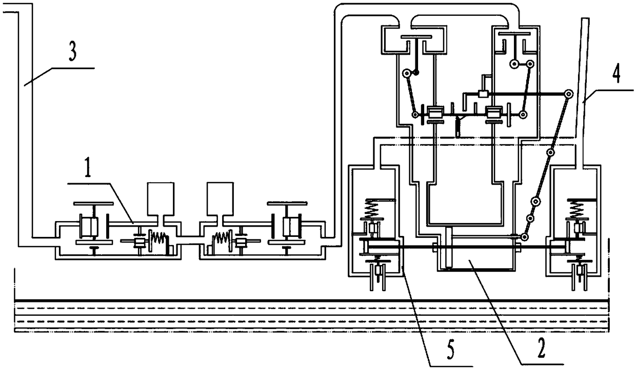
[0027] Embodiment 2: as Figure 1~Figure 8 As shown, the above-mentioned pressurizing device 1 is used for a pressurized water pump, including at least one pressurized device 1, a plunger cylinder 2 and a water pump 5, and the water inlet pipe 3 of each pressurized device 1 is connected to the high-level water source port. The outlet pipe 4 is connected to the water pump 5, the push rod 202 of the plunger cylinder 2 is connected to the piston 501 of the water pump 5, the water inlet of the water pump 5 is connected to the low water source port, and the water outlet is connected to the user water supply pipe.

[0028] Preferably, the plunger cylinder 2 includes a plunger 201 and a push rod 202, the plunger 201 is placed in the plunger chamber 203, the push rod 202 is fixedly connected to the plunger 201, and one end of the extension is connected to the piston 501, and the plunger chamber 203 are provided with water inlet and outlet 204 .

[0029] Preferably, the above-mentione...


PUM


Abstract

Disclosed is a water suction pump high-pressure pressurization device. The water suction pump high-pressure pressurization device comprises at least two pressurization devices, wherein the pressurization devices are connected in series. A water inlet of the first pressurization device is connected to a high-level water source, a water outlet of the first pressurization device is connected to a water inlet of the next-stage pressurization device, and a water inlet of the former-stage pressurization device is larger than that of the next-stage pressurization device. According to the water suction pump high-pressure pressurization device, the pressurization devices which are connected in series are used, the quantity of water flow is gradually reduced, the water outlet pressure is increased step by step, a power source is greatly improved, and therefore one-way pressurization can be achieved, high-lift water can be obtained, water power serves as the power source, the cost is low, and the water potential utilization ratio is improved. The water suction pump high-pressure pressurization device further has the advantages of being simple in structure, low in cost and environmentally friendly. Water serves as the power source, no pollution is caused, the cost is lower, the environment is better protected, and the water power utilization ratio is greatly improved.

Description

technical field [0001] The invention belongs to the technical field of pressurized water pumps, and relates to a high-pressure pressurization device for a water pump. Background technique [0002] The existing water pump provides the power source through the motor, and the motor drives the water-pressing mechanism inside the pump. The water-pressing mechanism quickly and briefly pushes the water in the pump to move forward to realize the pumping of the pump. For high-lift pumping, this method consumes power Big, expensive, and not environmentally friendly. Contents of the invention [0003] The technical problem to be solved by the present invention is to provide a high-pressure pressurizing device for a water pump, which can realize single-channel pressurization, obtain high-lift water, use water energy as a power source, and have low cost, so as to overcome the problems existing in the prior art. [0004] The technical solution adopted by the present invention is: a hig...

Claims


Application Information

Patent Timeline
Patent Type & Authority Patents(China)
IPC IPC(8): F04B53/00F04B49/08
CPCF04B49/08F04B53/00
Inventor 郭会郭革委郭春
Owner 南通和信工程勘测设计院有限公司
Why Eureka
Try Eureka