Electronic product placement frame

A technology for electronic products and placement racks, applied in the direction of machines/supports, supporting machines, mechanical equipment, etc., can solve the problems of inability to adjust, high use limitations, poor adaptability, etc., to reduce use limitations and improve adaptability. , the effect of improving reliability

Inactive Publication Date: 2017-11-10
YANCHENG SANDING ELECTRONICS TECH CO LTD
View PDF0 Cites 9 Cited by
  • Summary
  • Abstract
  • Description
  • Claims
  • Application Information

AI Technical Summary

Problems solved by technology

[0002] As we all know, the electronic product placement rack is an auxiliary device used to place electronic products during use to make users more convenient. It has been widely used in the field of electronic product use; the existing electronic product placement The frame includes a placement board, a top board, four sets of brackets and a bottom board. The bottom end of the placement board is connected to the front side of the top board, and a limiting board is arranged under the front side of the placement board. The rear side is connected to the right rear side, and the bottom ends of the four sets of brackets are all installed on the top of the bottom plate; when the existing electronic product placement rack is used, the electronic product is placed above the limit plate so that it can be supported by the placement plate; In the use of the existing electronic product racks, it was found that the height of the top plate was fixed and could not be adjusted, resulting in poor adaptability; and the angle between the placement plate and the top plate was fixed and could not be adjusted, resulting in high limitations in use; and the top plate could not be adjusted. rotation, resulting in less practical

Method used


Image

  • Electronic product placement frame
  • Electronic product placement frame
  • Electronic product placement frame

Examples


Embodiment Construction

[0014] The specific embodiments of the present invention will be described in further detail below in conjunction with the drawings and embodiments. The following examples are used to illustrate the present invention, but not to limit the scope of the present invention.

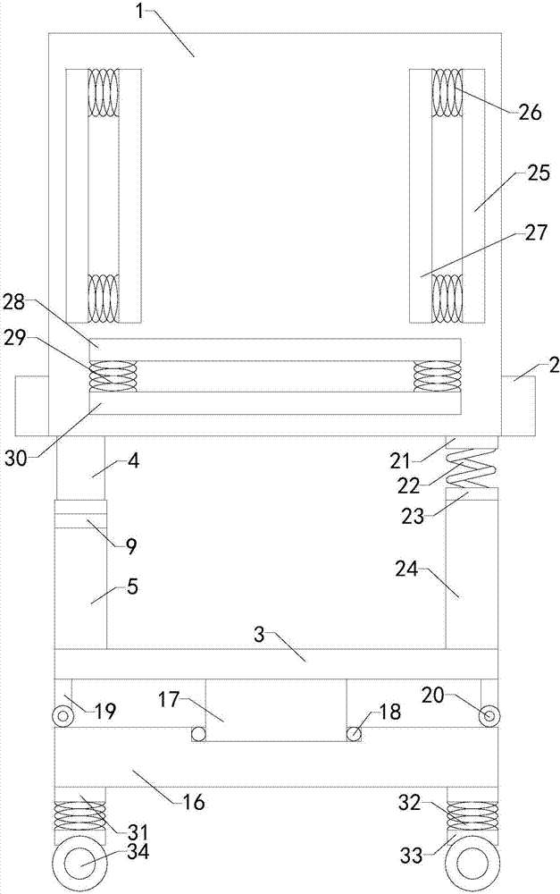
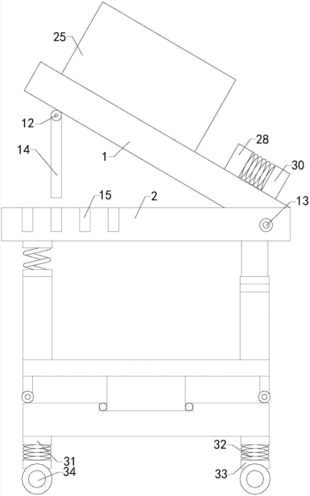
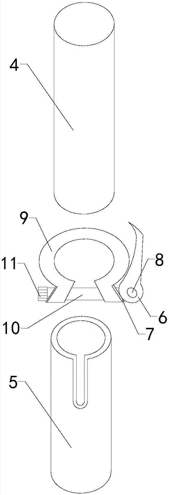
[0015] Such as Figure 1 to Figure 3 As shown, an electronic product placement rack of the present invention includes a placement plate 1, a top plate 2, four sets of brackets, and a bottom plate 3; two sets of brackets in the four sets of brackets all include insert 4 and insert 5, two sets of inserts The top ends of the two sets of intubation tubes are respectively connected to the left front and right back sides of the bottom of the top plate. The bottom ends of the two sets of intubation tubes are installed on the top of the bottom plate. There are notches on the side walls. The two sets of intubation tubes are equipped with quick-release pipe clamps, and the two sets of quick-release pipe clamps are locate...


PUM


Abstract

The present invention relates to the technical field of electronic product placement attachments, in particular to an electronic product placement rack, the height of the top plate can be adjusted to improve its adaptability; and the angle between the placement plate and the top plate can be adjusted to reduce its use limitation; and The top plate can be rotated to improve its practicality; includes a placement plate, top plate, four sets of brackets and a bottom plate; two sets of four sets of brackets include posts and cannulae, and two sets of quick release tube clips include quick release handles , handle seat, lower rotating shaft and quick-release clamp, the quick-release clamp is equipped with a quick-release lever, and the left end of the quick-release lever is provided with a nut; it also includes an upper rotating shaft, a middle rotating shaft and a connecting rod, and there are multiple sets of grooves on the top of the top plate ; It also includes a support plate and a rotating column, a placement groove is arranged on the top of the support plate, ball bearings are arranged in the placement groove, and two sets of pillars and two sets of pulleys are also included.

Description

Technical field [0001] The present invention relates to the technical field of electronic product placement accessory devices, in particular to an electronic product placement rack. Background technique [0002] As we all know, the electronic product placement rack is an auxiliary device used to place electronic products during the use process to make it more convenient for users. It has been widely used in the field of electronic product use; existing electronic product placement The rack includes a placement board, a top board, four sets of brackets and a bottom board. The bottom end of the placement board is connected to the front side of the top board, and a limit board is set under the front side of the placement board. The tops of the four sets of brackets are respectively connected to the left front side, right front side and left side of the bottom end of the top board. The rear side and the right rear side are connected, and the bottom ends of the four sets of brackets a...

Claims


Application Information

Patent Timeline
Patent Type & Authority Applications(China)
IPC IPC(8): F16M11/04F16M11/10F16M11/16F16M11/26
CPCF16M11/041F16M11/10F16M11/16F16M11/26F16M2200/048
Inventor 赵圣铭李彦龙
Owner YANCHENG SANDING ELECTRONICS TECH CO LTD
Why Eureka
Try Eureka