A kind of oil-pneumatic torsion spring

A torsion spring, oil and gas technology, applied in the direction of spring, spring/shock absorber, gas-liquid shock absorber, etc., can solve the problems of oil and gas mutual channeling, affecting the spring rebound effect, non-adjustment, etc., to enhance the compression resistance performance, The effect of prolonging the sealing period and preventing the mutual channeling of oil and gas

Active Publication Date: 2019-11-01
安徽东华弹簧有限公司
View PDF6 Cites 0 Cited by
  • Summary
  • Abstract
  • Description
  • Claims
  • Application Information

AI Technical Summary

Problems solved by technology

[0003] Traditional torsion springs are mostly fully mechanical torsion springs, whose stiffness is linear and cannot be adjusted, and the damping coefficient and resilience of the spring cannot be determined, so it cannot effectively attenuate vibration
The rigid column of the spring is prone to noise after being twisted under force, and it is easy to break if it is too strong. Long-term use will also easily cause its stiffness and resilience to decay. Therefore, fully mechanical torsion springs cannot be used for a long time in many occasions.
[0004] The prior art, such as the Chinese invention authorized patent document, authorized announcement number CN 104930104 B, discloses an oil-gas torsion spring, which is composed of a cylinder, a torsion shaft, a floating piston and an end cover, and the inner wall of the cylinder and the outer wall of the torsion shaft A closed annular cavity is formed between them. The annular cavity is divided into two oil chambers and two air chambers. The two oil chambers are adjacent and separated by a swing arm fixed on the torsion shaft. A damping hole is opened on the swing arm to communicate with the two The oil chamber and the two air chambers are separated by a fixed baffle fixed on the inner wall of the cylinder, and the oil chamber is separated from the adjacent air chamber by a floating piston that can slide freely along the inner wall of the cylinder and the outer wall of the torsion shaft. Force torsion, the change of the size of the two oil chambers causes the floating piston to slide, which causes the pressure of the two air chambers to be uneven and produces a reaction force on the floating piston, thereby attenuating the torsion of the torsion shaft
The oil-pneumatic torsion spring of this invention has the advantages of simple manufacture, smart design, and easy operation; however, under frequent torsional force, the force of the hydraulic oil in the oil chamber is very frequent and changeable, which will cause the hydraulic oil to slowly penetrate into the sealing part , thus affecting the rebound effect of the spring, and more seriously, it may lead to oil and gas mutual channeling

Method used


Image

  • A kind of oil-pneumatic torsion spring
  • A kind of oil-pneumatic torsion spring
  • A kind of oil-pneumatic torsion spring

Examples


Embodiment 1

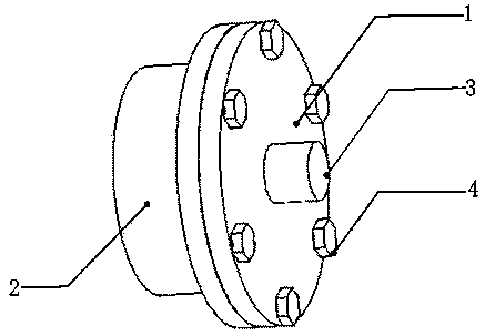
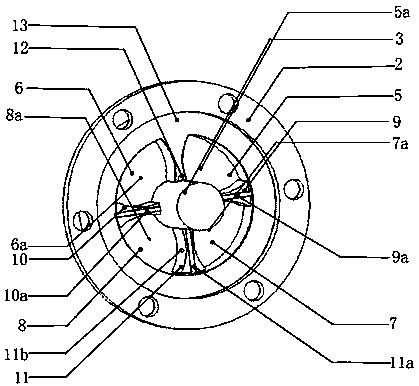
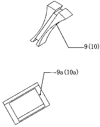
[0027] Such as Figure 1-7 As shown, an oil-pneumatic torsion spring includes a cylinder 2, a torsion shaft 3, a first floating piston 9, a second floating piston 10, and an end cover 1. One end of the torsion shaft 3 is designed with a counterbore, and the other end is designed with a torsion shaft swing arm. 11. A closed annular cavity is formed between the inner wall of the cylinder 2 and the outer wall of the torsion shaft 3. The annular cavity is divided into an air chamber and an oil chamber by the first floating piston 9 and the second floating piston 10. The baffle divides the air chamber into a symmetrical first air chamber 5 and a second air chamber 6, and the oil chamber is divided into a symmetrical first oil chamber 8 and a second oil chamber 9 by the swing arm 11 fixed on the torsion shaft 3 And it can be connected through the damping hole 11b provided on the swing arm, the damping hole 11b can make the hydraulic oil in the oil chamber spread in the two oil chamb...

Embodiment 2

[0038] Such as Figure 1-7 As shown, when assembling the oil and gas spring, it is necessary to apply sealant on each sealing ring, gasket, and sealing ring to improve its sealing effect. The addition of sealing layers in each sealing environment not only improves its sealing degree, but also prevents frequent pressure and The oil and gas crossover caused by the change can also reduce the working strength of the sealing ring, sealing gasket and sealing ring, and prolong their service life, thereby reducing the cost.

[0039] Such as Figure 1-7 As shown, after the assembly of the oil-gas spring, it is necessary to fill the oil-air chamber with oil and gas. At this time, it is necessary to ensure that the two air chambers are filled with the same amount of inert gas, because the amount of hydraulic oil in the two oil chambers is in a dynamic pressure balance. They can complement each other through damping holes, and the inert gas in the two gas chambers cannot change their res...


PUM


Abstract

The invention provides an oil gas torsion spring, and belongs to the field of springs. The oil gas torsion spring comprises a cylinder barrel, a torsion shaft, floating pistons and an end cover. A closed annular cavity is formed between the inner wall of the cylinder barrel and the outer wall of the torsion shaft. The annular cavity is divided by the first floating piston and the second floating piston into a gas chamber and an oil chamber, a fixed baffle fixedly connected to the inner wall of the cylinder barrel divides the gas chamber into a first gas chamber body and a second gas chamber body which are symmetric, a swinging arm fixedly connected to the torsion shaft divides the oil chamber into a first oil chamber body and a second oil chamber body which are symmetric, the oil chamber bodies are connected through damping holes, and hydraulic oil is led into the oil chamber. Inert gases are led into the gas chamber, and the end cover penetrates the torsion shaft to be fixedly connected with the cylinder barrel through a bolt. According to the oil gas torsion spring, the torsion rigidity and damping coefficient can be automatically adjusted, and accordingly, torsion vibration and torque can be effectively buffered and attenuated; and meanwhile, various sealing systems are internally coated with sealing layers, mutual oil and gas channeling can be effectively prevented, and therefore the oil gas torsion spring is efficient and universal.

Description

technical field [0001] The invention relates to the technical field of springs, in particular to an oil-pneumatic torsion spring. Background technique [0002] Torsion springs (torsion springs) use the principle of leverage to twist or rotate elastic materials that are soft and tough, so that they have great mechanical energy. It is a spring that is subjected to torsional deformation, and its working part is either tightly wound or separately wound. The end structure of the torsion spring is processed into various shapes of torsion arms, from single torsion to double torsion, and even the deformation of various torsion bars can be formed according to the design. Torsion springs are often used in balance mechanisms in machinery, and are widely used in industrial production such as automobiles, machine tools, and electrical appliances. [0003] Most traditional torsion springs are fully mechanical torsion springs, whose stiffness is linear and cannot be adjusted, and the dam...

Claims


Application Information

Patent Timeline
Patent Type & Authority Patents(China)
IPC IPC(8): F16F9/36F16F9/06
CPCF16F9/06F16F9/368
Inventor 胡光琼
Owner 安徽东华弹簧有限公司
Why Eureka
Try Eureka