Method for adjusting propagation trajectory of Airy beam at large scale

An Airy beam, large-scale technology, applied in optics, optical components, instruments, etc., can solve problems such as limiting the control range of Airy beam transmission trajectory

Inactive Publication Date: 2017-11-14
ZHEJIANG NORMAL UNIVERSITY
View PDF4 Cites 13 Cited by
  • Summary
  • Abstract
  • Description
  • Claims
  • Application Information

AI Technical Summary

Problems solved by technology

This greatly limits the control range of the Airy beam transmission trajectory

Method used


Image

  • Method for adjusting propagation trajectory of Airy beam at large scale
  • Method for adjusting propagation trajectory of Airy beam at large scale
  • Method for adjusting propagation trajectory of Airy beam at large scale

Examples


Embodiment Construction

[0035] The present invention will be further described below in conjunction with the accompanying drawings and embodiments.

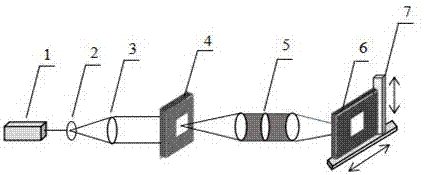
[0036] figure 1Schematic diagram of preparing a large-scale cubic phase mask for a holographic micro-output system. It includes: a light source (1), a beam expander collimation system (2, 3), an SLM (4), a microlens (5), a recording medium (6), and a digitally controlled stepping platform (7).

[0037] The experiment implementation process is as follows:

[0038] 1. The light source (1) is collimated into parallel light through the beam expansion and collimation system (2, 3), and is incident on the SLM (4).

[0039] 2. The system uses the SLM (4) to load the hologram, and the hologram is miniaturized onto the recording medium (6) through the microlens (5).

[0040] 3. The digitally controlled stepping platform (7) moves the recording medium (6) to realize splicing of holograms and the preparation of large-scale cubic phase masks (6).
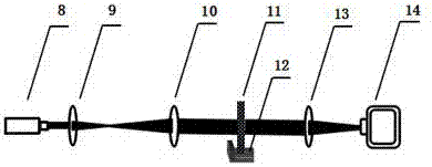
[0041] fig...


PUM


Abstract

The invention discloses a method for adjusting the propagation trajectory of an Airy beam at a large scale. Based on the diffraction theory and the definition of an Airy function, under the condition that the center of an Airy beam cubic phase mask deviates from the optical axis of a Fourier transform lens, a peak trajectory expression of an Airy beam is derived, and the focal length of the Fourier transform lens and the transverse and longitudinal dislocation of the center of the phase mask deviating from the optical axis of the Fourier transform lens are determined as factors affecting the propagation trajectory of the Airy beam. A large-scale cubic phase mask is prepared through a holographic microfilm output system. The transverse and longitudinal dislocation of the center of the phase mask deviating from the optical axis of the Fourier transform lens is increased. The initial emission angle of an Airy beam can be adjusted in a wide range. Thus, the propagation trajectory of an Airy beam can be adjusted in a wide range. An Airy beam is generated using a large cubic phase mask in the invention. The range of initial emission angle of an Airy beam is greatly increased. A novel scheme is provided for substantial adjustment of the propagation trajectory of an Airy beam.

Description

technical field [0001] The invention relates to a transmission track control technology of a light beam, and discloses a method for large-scale regulation and control of the transmission track of an Airy light beam. Based on the definition of the cubic phase Fourier transform that produces an Airy beam, the peak trajectory of the Airy beam is deduced when the center of the phase mask deviates from the optical axis of the Fourier transform lens. Theoretical derivation results show that the greater the misalignment between the optical axis of the Fourier transform lens and the center of the phase plate, the greater the controllable range of the transmission trajectory of the Airy accelerated beam. [0002] The invention utilizes the holographic printing technology to manufacture a large-sized phase mask plate, which can regulate the transmission track of the Airy beam in a large range. The flexible and controllable transmission trajectory provides a more practical accelerated l...

Claims


Application Information

Patent Timeline
Patent Type & Authority Applications(China)
IPC IPC(8): G02B5/30G02B27/28
CPCG02B5/3083G02B27/28
Inventor 吴琼
Owner ZHEJIANG NORMAL UNIVERSITY
Why Eureka
Try Eureka