
Automatic molding equipment for lamp base plates

A technology of forming equipment and bottom plate, applied in the field of automatic forming equipment of lamp bottom plate, can solve the problems of poor punching effect, inconvenient replacement, affecting efficiency, etc., and achieve the effects of smooth feeding, good versatility and good punching effect.

Pending Publication Date: 2017-11-17
苏州申达洁净照明股份有限公司
View PDF11 Cites 1 Cited by
  • Summary
  • Abstract
  • Description
  • Claims
  • Application Information

AI Technical Summary

Problems solved by technology

However, the existing forming abrasives usually have a fixed structure, so they can only be stamped for one product. If you need to stamp other products with different needs, you need to replace different molds
For the lamp frame, due to its small area and the number of punching holes required on the surface, there are not many types that can be changed. It may be acceptable by changing the mold, but for the lamp base plate, there are many types. , not only need to prepare all kinds of corresponding molds, but also it is very inconvenient to replace, and even some products cannot be completed on a set of molds, which seriously affects the efficiency
Moreover, the upper and lower sides of both ends of the bottom plate of the lamp usually need to be punched into a stepped structure. The existing punching of the two ends of the bottom plate is also completed by two different stations at the front and back. Not only the punching effect is not good, but also it is not easy to discharge waste.

Method used


Image

  • Automatic molding equipment for lamp base plates
  • Automatic molding equipment for lamp base plates
  • Automatic molding equipment for lamp base plates

Examples


Embodiment Construction

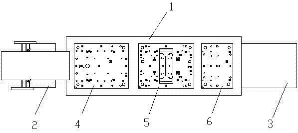
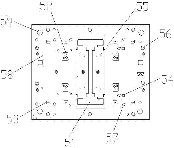
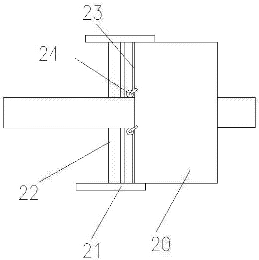
[0030] The present invention will be further described below in conjunction with the accompanying drawings of the specification.

[0031] Such as Figure 1-Figure 7 As shown, an automatic molding equipment for the bottom plate of a lamp includes a base 1. The surface of the base 1 is fixedly provided with a first lower mold 4, a second lower mold 5, and a third lower mold 6, and the three lower molds are provided with multiple A forming punching hole of different shapes, including a first forming punching hole 52, a second forming punching hole 53, a third forming punching hole 54, a fourth forming punching hole 55 and a fifth forming punching hole 56, and the second lower forming hole The mold 5 is also provided with a detachable dumbbell-shaped punching plate 51, and the upper and lower ends of the dumbbell-shaped punching plate 51 are provided with symmetrical steps, and an upper mold is provided above the base 1, and The upper die is provided with a punch corresponding to th...


PUM


Abstract

The invention discloses automatic molding equipment for lamp base plates. The automatic molding equipment comprises a base, a first lower mold, a second lower mold and a third lower mold are fixedly arranged on the surface of the base, the three lower molds are provided with multiple kinds of molding punching holes in different shapes, and the molding punching holes comprise the first molding punching hole, the second molding punching hole, the third molding punching hole, the forth molding punching hole and the fifth molding punching hole; the second lower mold is further provided with a detachable dumbbell-shaped punching plate, and the upper and lower ends of the dumbbell-shaped punching plate are provided with symmetrical step parts; an upper mold is arranged above the base and is provided with puncher pins corresponding to the molding punching holes and the dumbbell-shaped punching plate in position and shape; and a feeding mechanism is arranged at the front end of the base, and a receiving material conveying belt is arranged at the back end of the base.

Description

Technical field [0001] The invention relates to an automatic molding equipment for a lamp bottom plate, belonging to the technical field of lamp production molds. Background technique [0002] In the production process of lamps and lanterns, the surface of the bottom plate needs to be punched to form punching holes or slots of different shapes, and different products have different numbers and positions of punching holes or slots on the bottom plate. However, the existing forming abrasive tools are usually fixed in structure, so only one product can be stamped and formed. If other products with different needs need to be stamped, different molds need to be replaced. For the lamp frame, due to its small area, the number of punching holes on the surface is also small, so there are not many types that can be changed. It may be reluctant to accept it by replacing the mold, but for the lamp bottom plate, there are many types , Not only need to prepare various corresponding molds, but...

Claims


Application Information

Patent Timeline
Patent Type & Authority Applications(China)
IPC IPC(8): B21D37/02
CPCB21D37/02
Inventor 张土林
Owner 苏州申达洁净照明股份有限公司
Learn More