Die casting machine and shaping method of solid-liquid coexisting metal

A technology of solid-liquid coexistence and die-casting machine, which is applied in the field of die-casting machines and the forming of metals in solid-liquid coexistence, and can solve problems such as pressure imparted by difficult solid-liquid coexistence metals

Active Publication Date: 2017-11-17
TOSHIBA MASCH CO LTD
View PDF10 Cites 3 Cited by
  • Summary
  • Abstract
  • Description
  • Claims
  • Application Information

AI Technical Summary

Problems solved by technology

On the other hand, in the configuration in which pressure is applied to the solid-liquid coexisting state metal by the plunger as in Patent Document 1, it is difficult to apply sufficient pressure to the solid-liquid coexisting state metal.
In addition, in the configuration in which the metal in the solid-liquid coexistence state is conveyed between the molds in which the mold is opened and the metal in the solid-liquid coexistence state is applied by clamping the molds as in Patent Document 2, the direction of mold opening is limited to the vertical direction, and the solid-liquid coexistence state must be configured. Dedicated equipment for metal forming in liquid coexistence state

Method used


Image

  • Die casting machine and shaping method of solid-liquid coexisting metal
  • Die casting machine and shaping method of solid-liquid coexisting metal
  • Die casting machine and shaping method of solid-liquid coexisting metal

Examples


no. 1 approach >

[0044] (The overall structure of the die casting machine)

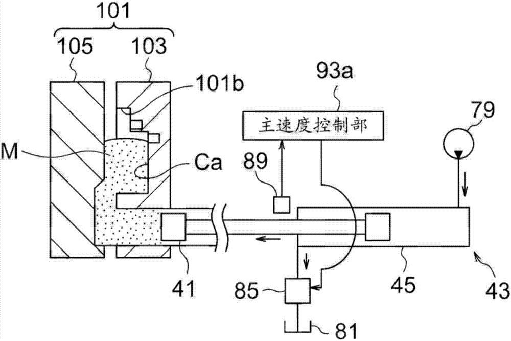
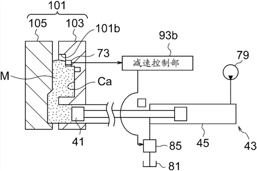
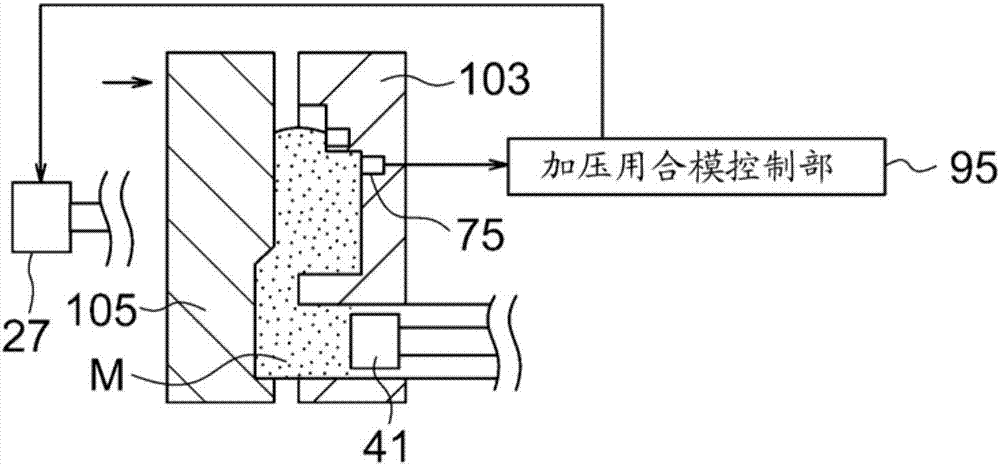
[0045] figure 1 It is a partially cutaway side view showing the configuration of a main part of the die casting machine 1 according to the first embodiment of the present invention.

[0046] Die casting machine 1 injects liquid metal (melt) or solid-liquid coexisting metal into mold 101 (cavity Ca and other spaces. The same applies below.) and solidifies the metal in mold 101 to manufacture die castings (molded parts) . It should be noted that the die casting machine 1 can be used for forming either liquid metal or metal in a solid-liquid coexistence state, but in the following description, the configuration for forming semi-solidified metal as an example of a metal in a solid-liquid coexistence state will be mainly described. and steps. The metal is, for example, aluminum or an aluminum alloy.

[0047] The die 101 includes, for example, a fixed die 103 and a movable die 105 . In the description of this embodimen...

no. 2 approach >

[0236] Figure 11 are the symbols showing the configuration of the main parts of the die casting machine 201 of the second embodiment and figure 1 corresponding figure.

[0237] In the first embodiment, the injection driving unit 43 of the injection device 9 is a hydraulic type. On the other hand, in the second embodiment, the injection driving unit 243 of the injection device 209 is an electric type. Other than that, the second embodiment is the same as the first embodiment.

[0238] The electric injection driving unit 243 can have various configurations. In the illustrated example, the injection drive unit 243 has a rotary motor 244 and a transmission mechanism 245 that converts the rotation of the motor 244 into a translational motion and transmits it to the plunger 41 .

[0239] The transmission mechanism 245 is comprised by the screw mechanism, for example, and has the screw shaft 245a, and the nut 245b screwed together with the screw shaft 245a. The screw shaft 245 ...


PUM


Abstract

The invention provdies a die casting machine, which can properly applying pressure to a solid-liquid coexisting metal, and includes a clamping device 7 which opens and closes and clamps a pair of die halves 101, an injection apparatus 9 which performs injection to the pair of die halves by making a plunger 41 move forward in a sleeve 39 communicated with a space between the pair of die halves, and a control device 47 which controls the clamping device 7 and injection apparatus 9. The control device 47 includes an injection control part 93 and press-use clamping control part 95. The injection control part controls the injection apparatus so as to start the injection in a state where the pair of die halves face each other through a gap. The press-use clamping control part controls the clamping device so that the die contact and clamping are carried out after the start of injection. Further, the injection control part performs control for decelerating the plunger before the plunger stops.

Description

technical field [0001] The invention relates to a die-casting machine and a forming method of a solid-liquid coexisting state metal. It should be noted that the solid-liquid coexisting state metal may be either semi-solidified metal in which liquid metal is cooled to a solid-liquid coexisting state, or semi-molten metal in which solid metal is heated to become a solid-liquid coexisting state. Background technique [0002] A technique for shaping a metal in a solid-liquid coexistence state is known. For example, in Patent Document 1, in a die-casting machine having the same structure as a normal die-casting machine for forming liquid metal (melt), semi-solidified metal is supplied to a sleeve passing between molds after mold clamping, and a plunger Forming is performed by injecting the semi-solidified metal inside the sleeve between the molds. In addition, in Patent Document 2, semi-molten metal is conveyed between open molds (injection is not performed), and then the molds...

Claims


Application Information

Patent Timeline
IPC IPC(8): B22D17/04
CPCB22D17/007B22D17/04B22D17/002B22D17/10B22D17/203B22D17/26B22D17/32
Inventor 中田光荣相田悟豊岛俊昭
Owner TOSHIBA MASCH CO LTD
Why Eureka
Try Eureka