
Brake negative pressure generating device for vehicle

Active Publication Date: 2014-07-03
HYUNDAI MOTOR CO LTD
View PDF2 Cites 4 Cited by
  • Summary
  • Abstract
  • Description
  • Claims
  • Application Information

AI Technical Summary

Benefits of technology

The brake negative pressure generating deice for the vehicle described in this patent helps to always generate appropriate negative pressure and ensures safety for driving the car. It does not require a vacuum pump, which can save weight and cost.

Problems solved by technology

However, there is a limit to compressing drawn air and supplying it to the engine only by the pressure of exhaust gas depending on the vehicle's traveling situation.
In the case of a vehicle using the aforementioned turbocharger or supercharger, if a brake pedal is operated after the engine goes into Wide Open Throttle (WOT) mode by stepping on the accelerator pedal as hard as possible, static pressure in the intake manifold cannot be properly released, though for a short period of time.
This leads to a failure to generate sufficient negative pressure for brake force boosting, and hence the brake may be pulled back.
Moreover, when driving the vehicle on hilly roads, negative pressure generated in the intake manifold may not be sufficient for brake force boosting.

Method used


Image

  • Brake negative pressure generating device for vehicle
  • Brake negative pressure generating device for vehicle

Examples


Embodiment Construction

[0027]Reference will now be made in detail to various embodiments of the present invention(s), examples of which are illustrated in the accompanying drawings and described below. While the invention(s) will be described in conjunction with exemplary embodiments, it will be understood that present description is not intended to limit the invention(s) to those exemplary embodiments. On the contrary, the invention(s) is / are intended to cover not only the exemplary embodiments, but also various alternatives, modifications, equivalents and other embodiments, which may be included within the spirit and scope of the invention as defined by the appended claims.

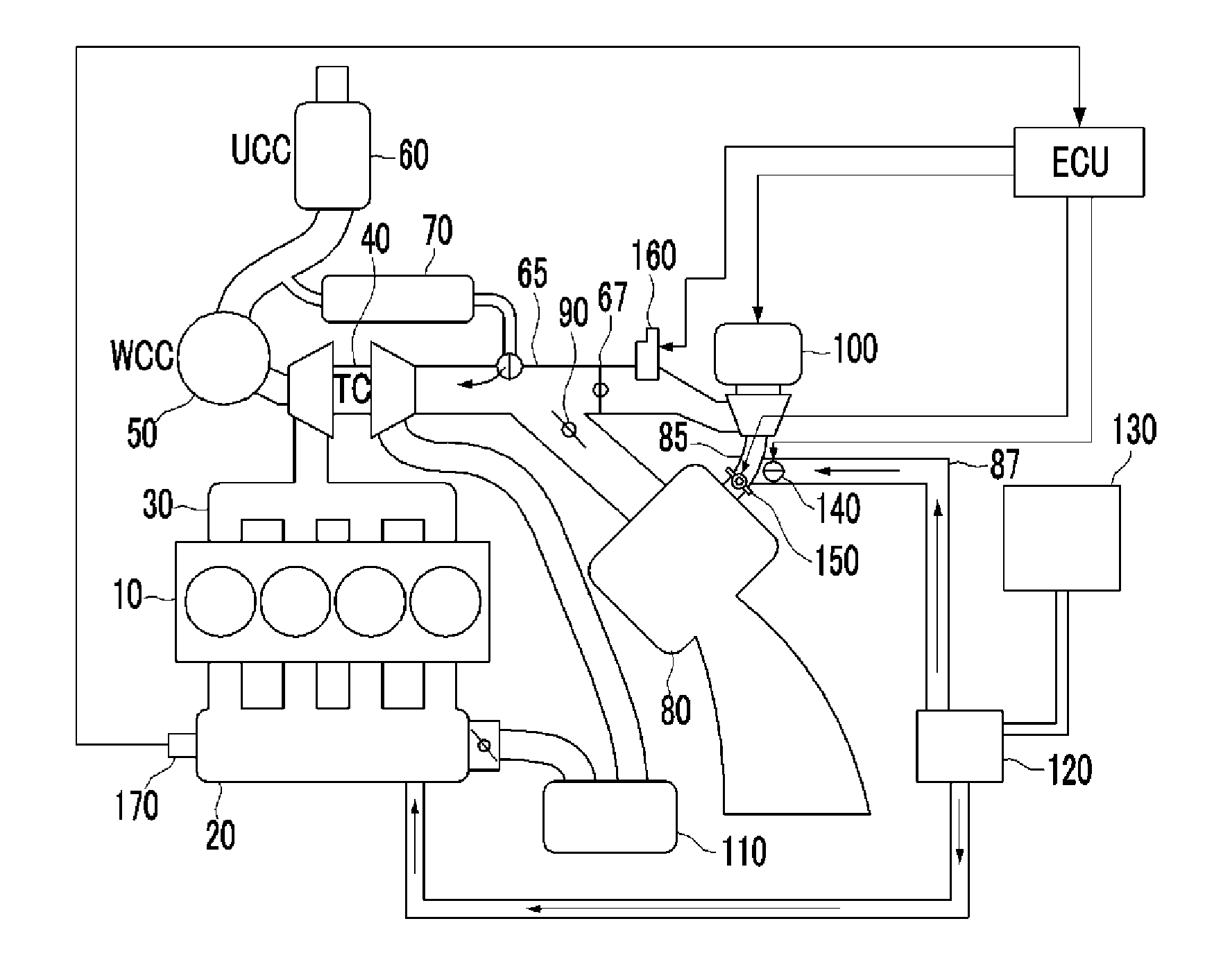
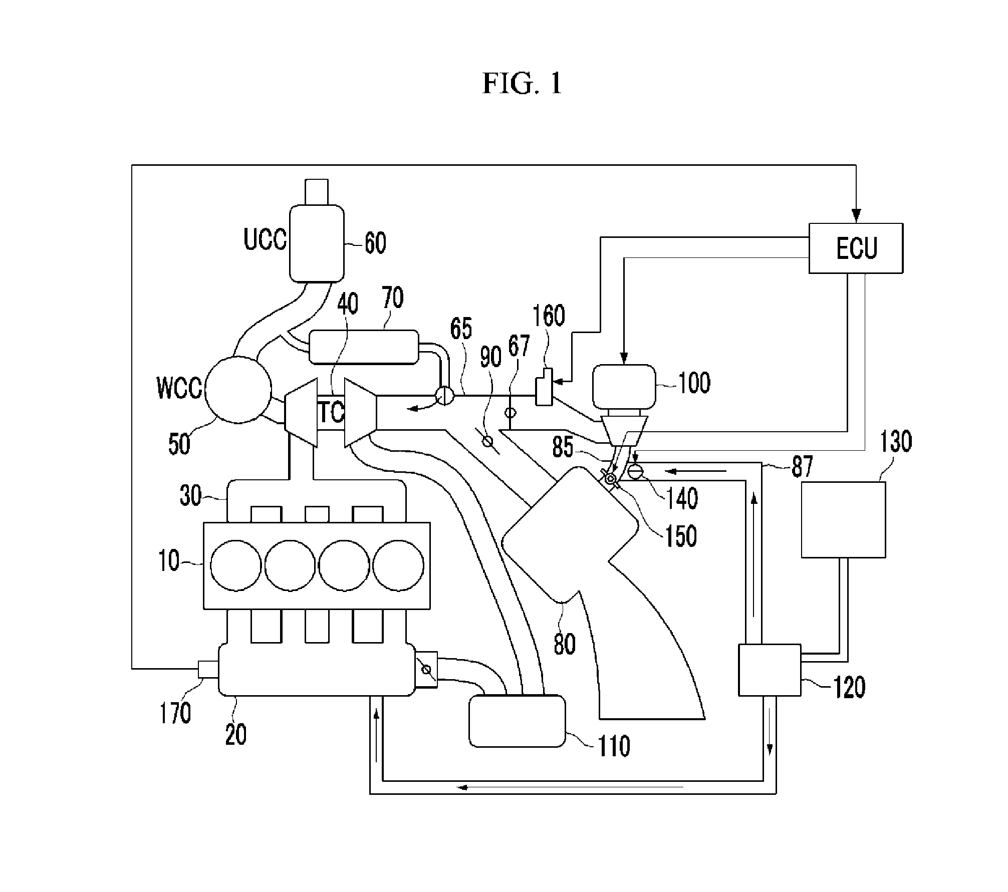
[0028]Referring to FIG. 1, an intake manifold 20 for drawing air or an air-fuel mixture is connected to a cylinder block 10 forming a combustion chamber of an engine, and an exhaust manifold 30 is connected to the cylinder block 10 to discharge exhaust gas generated by combustion in the combustion chamber from the cylinder block 10.

[0...


PUM


Abstract

A brake negative pressure generating device of a vehicle includes: an electrically-driven supercharger for drawing in, compressing, and supplying outside air; a vacuum chamber connected to an inlet opening of the electrically-driven supercharger and supplying negative pressure for brake force boosting; a negative pressure supply passage for connecting the inlet opening of the electrically-driven supercharger and the vacuum chamber; and a first negative pressure control valve for opening and closing an inlet passage. Accordingly, the electrically-driven supercharger is run to supplement brake negative force if the brake negative force is not sufficient.

Description

CROSS-REFERENCE TO RELATED APPLICATION[0001]The present application claims priority of Korean Patent Application Number 10-2012-0155384 filed Dec. 27, 2012, the entire contents of which application is incorporated herein for all purposes by this reference.BACKGROUND OF INVENTION[0002]1. Field of Invention[0003]The present invention relates to a brake negative pressure generating device for a vehicle, and more particularly, to a brake negative pressure generating device which generates brake negative pressure by a supercharger when required.[0004]2. Description of Related Art[0005]In general, a vehicle draws external air therein, mixes the air with fuel, and supplies the mixture to an engine, and the engine gets the power required to drive the vehicle by combusting the mixture of air and fuel.[0006]To achieve desired engine output and combustion efficiency, it is necessary to supply a sufficient amount of external air for combustion while generating power by driving the engine. Thus,...

Claims


Application Information

Patent Timeline
IPC IPC(8): F02B33/02
CPCF02B33/02F02B37/04F02B37/10F02B37/16Y02T10/12B60T8/171B60T13/52F02M35/10
Inventor KIM, YOON JOOLIM, HYUN JUNHAN, DONG HEEHAN, SEUNG KOOKPARK, JONG IL
Owner HYUNDAI MOTOR CO LTD
Learn More