Adjustable welding clamp device

A welding fixture and adjustable technology, applied in the field of tooling and fixtures, can solve the problems of inability to locate and adjust the welding position, fail to achieve the pass rate of the shock absorber, increase the difficulty of welding, etc., to achieve convenient positioning and adjustment, convenient assembly, The effect of reducing the difficulty of welding

Inactive Publication Date: 2017-11-17
TAIZHOU HUAFENG TECH EQUIP
View PDF0 Cites 0 Cited by
  • Summary
  • Abstract
  • Description
  • Claims
  • Application Information

AI Technical Summary

Problems solved by technology

[0002] In the process of modern industrial production, fixtures have been widely used in the process of workpiece welding. The accuracy of welding and the dimensional accuracy of workpieces are directly related to the production efficiency and the pass rate of workpiece products, while the traditional welding fixtures only play a role. The function of clamping, however, cannot be used for welding of all products through hardware clamping alone, and cannot meet the needs of modern production. Fixtures, unable to locate and adjust the welding position, resulting in the port of the elbow of many shock absorbers protruding outside the assembly hole of the flange. This kind of shock absorber is often easily damaged by a little external force and cannot achieve shock absorption. The pass rate of the shock absorber, while the current flange elbow shock absorber needs to set the port of the elbow of the shock absorber on the inner wall of the assembly hole on the flange, if only relying on the workmanship Cooperate with adjusting the welding position, it increases the difficulty of welding and increases the production cost, and the production efficiency is low

Method used


Image

  • Adjustable welding clamp device
  • Adjustable welding clamp device
  • Adjustable welding clamp device

Examples


Embodiment Construction

[0011] The present invention will be described in further detail below in conjunction with the accompanying drawings and specific embodiments.

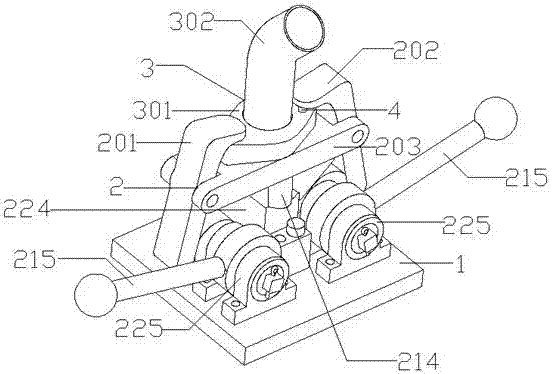
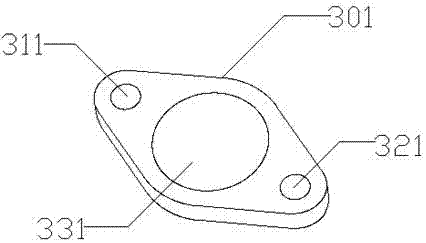
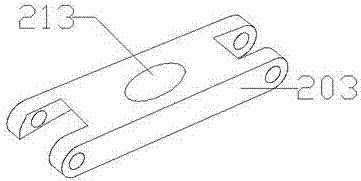
[0012] Such as Figure 1 ~ Figure 3 As shown in the structural diagram of the present invention, an adjustable welding fixture device includes a base 1, a welding adjustment clamping mechanism 2 and a shock absorber 3, and the welding adjustment clamping mechanism 2 is arranged above the base 1 The welding adjustment clamping mechanism 2 includes a first mechanical arm 201, a second mechanical arm 202, a support 203, a lifting device 204 and an adjustment mechanism 205; the adjustment mechanism 205 includes a pressure rod 215 and a regulator 225; The shock absorber 3 includes a flange 301 and a shock absorber body 302; the flange 301 is provided with a first fixing hole 311, a second fixing hole 321 and an assembly hole 331; the shock absorber body 302 passes through the assembly The hole 331 is connected to the flange 301; the middl...


PUM


Abstract

The invention discloses an adjustable welding clamp device, which comprises a base (1), a welding adjustment clamping mechanism (2) and a shock absorber (3). The welding adjustment clamping mechanism is arranged above the base; the welding adjustment clamping mechanism It includes a first mechanical arm (201), a second mechanical arm (202), a support (203), a lifting device (204) and an adjustment mechanism (205); the adjustment mechanism includes a pressing rod (215) and a regulator (225); The shock absorber includes a flange (301) and a shock absorber body (302); the flange is provided with a first fixing hole (311), a second fixing hole (321) and an assembly hole (331); the shock absorber body is assembled by The hole is connected to the flange; the two ends of the support are connected to the first mechanical arm and the second mechanical arm. The invention adopts an adjustable welding fixture device, which is convenient for adjusting and positioning the nozzle of the shock absorber body on the inner wall of the assembly hole on the flange, so as to ensure the qualification rate of the shock absorber.

Description

technical field [0001] The invention relates to the technical field of tooling fixtures, in particular to an adjustable welding fixture device. Background technique [0002] In the process of modern industrial production, fixtures have been widely used in the process of workpiece welding. The accuracy of welding and the dimensional accuracy of workpieces are directly related to the production efficiency and the pass rate of workpiece products, while the traditional welding fixtures only play a role. The function of clamping, however, cannot be used for welding of all products through hardware clamping alone, and cannot meet the needs of modern production. Fixtures, unable to locate and adjust the welding position, resulting in the port of the elbow of many shock absorbers protruding outside the assembly hole of the flange. This kind of shock absorber is often easily damaged by a little external force and cannot achieve shock absorption. The pass rate of the shock absorber, ...

Claims


Application Information

Patent Timeline
Patent Type & Authority Applications(China)
IPC IPC(8): B23K37/053
CPCB23K37/0536
Inventor 黄光明
Owner TAIZHOU HUAFENG TECH EQUIP
Why Eureka
Try Eureka