Polishing machine with dust suction device

A dust collection device and polishing machine technology, applied in the field of polishing machines, can solve problems such as a large amount of dust, affecting lung function, and affecting the respiratory health of staff, so as to maintain respiratory health, improve integrity and efficiency, and reduce the degree of flying Effect

Inactive Publication Date: 2017-11-17
山东恒德智能装备科技有限公司
View PDF1 Cites 4 Cited by
  • Summary
  • Abstract
  • Description
  • Claims
  • Application Information

AI Technical Summary

Problems solved by technology

There are many types of existing polishing machines. Most polishing machines can only polish fixed products, and cannot adapt to the size of various products, so that the product is not polished completely. When polishing the product, a large amount of dust will appear, which is harmful to the work. Affect the respiratory health of personnel and affect lung function
Chinese patent CN 205734485U discloses a vacuum polishing machine, including a working platform, the left side of the working platform is connected to the pillar, the middle part of the pillar is connected to the pulley through the connecting rod, the right side of the pulley is connected to the connecting block through the connecting rod, and the connecting block The bottom is connected to the working platform through a telescopic rod, the right side of the connecting block is connected to the first connecting column, the right side of the first connecting column is connected to the second connecting column, the right side of the second connecting column is connected to the motor, and the grinding wheel is installed on the bottom of the motor. The middle part of the platform is equipped with a fixed seat, and the right side of the working platform is equipped with a dust collection cover. It is sucked into the dust collection box through the pipe to reduce the air pollution caused by wood polishing. However, if no proper measures are taken to deal with the dust in the dust collection box, it is still easy to affect the respiratory health of the staff.

Method used


Image

  • Polishing machine with dust suction device
  • Polishing machine with dust suction device

Examples


Embodiment Construction

[0021] The following will clearly and completely describe the technical solutions in the embodiments of the present invention with reference to the accompanying drawings in the embodiments of the present invention. Obviously, the described embodiments are only some, not all, embodiments of the present invention. Based on the embodiments of the present invention, all other embodiments obtained by persons of ordinary skill in the art without creative efforts fall within the protection scope of the present invention.

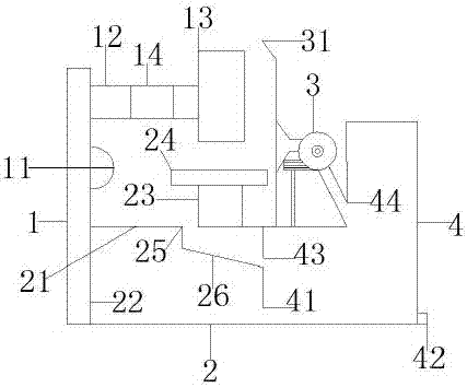
[0022] like Figure 1-2 As shown, a polishing machine with a dust suction device includes an operating table. The operating table includes a main operating table 1 and an operating auxiliary table 2. The operating main table 1 is fixedly connected to the operating auxiliary table 2. The operating main table 1 includes a blower 11, Frame 12 and polishing disc 13, frame 12 is provided with motor 14, and the output end of motor 14 is connected with polishing disc 13, ...


PUM


Abstract

The present invention relates to the technical field of polishing machines, and more specifically relates to a polishing machine with a dust suction device, which includes an operating table, the operating table includes a main operating table and an auxiliary operating table, and the main operating table includes a blower, a frame and a polishing disc , the operation sub-table includes the table, water tank, lifting device and support plate, adjust the lifting device to make the distance between the support plate and the polishing plate adapt to the size of the actual product, the dust suction fan sucks the dust into the dust box, the blower and The inlet increases the efficiency of dust entering the dust collection box, and the water tank reduces the flying degree of dust during subsequent processing; the invention is suitable for various product sizes, has more comprehensive dust collection, reduces the difficulty of subsequent processing, improves the working environment, and is suitable for popularization and use.

Description

technical field [0001] The invention relates to the technical field of polishing machines, in particular to a polishing machine with a dust suction device. Background technique [0002] Polishing machine, also known as grinding machine, is often used for mechanical grinding, polishing and waxing. Because the polishing disc and polishing agent work together and rub against the surface, it can achieve the purpose of removing paint surface pollution, oxide layer and shallow layer. There are many types of existing polishing machines. Most polishing machines can only polish fixed products, and cannot adapt to the size of various products, so that the product is not polished completely. When polishing the product, a large amount of dust will appear, which is harmful to the work. It affects the respiratory health of personnel and affects lung function. Chinese patent CN 205734485U discloses a vacuum polishing machine, including a working platform, the left side of the working plat...

Claims


Application Information

Patent Timeline
Patent Type & Authority Applications(China)
IPC IPC(8): B24B29/00B24B55/06B24B41/06
CPCB24B29/00B24B41/06B24B55/06
Inventor 张华彬张鹏张倩倩
Owner 山东恒德智能装备科技有限公司
Why Eureka
Try Eureka