
Infrared positioning device for heat-sensitive label printing paper

A technology of positioning device and thermal printer, applied in printing device, measuring device, using optical device, etc.

Pending Publication Date: 2017-11-17
XIAMEN JRP ELECTRONICS & TECH
View PDF14 Cites 0 Cited by
  • Summary
  • Abstract
  • Description
  • Claims
  • Application Information

AI Technical Summary

Problems solved by technology

[0008] The purpose of the present invention is to provide an improved thermal label printing paper infrared positioning device for the above-mentioned problems existing in the existing thermal printer paper positioning infrared device

Method used


Image

  • Infrared positioning device for heat-sensitive label printing paper
  • Infrared positioning device for heat-sensitive label printing paper

Examples


Embodiment Construction

[0015] The following embodiments will further illustrate the present invention in conjunction with the accompanying drawings.

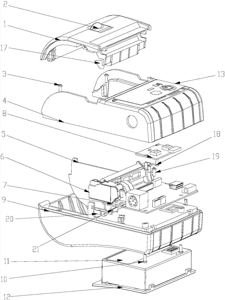
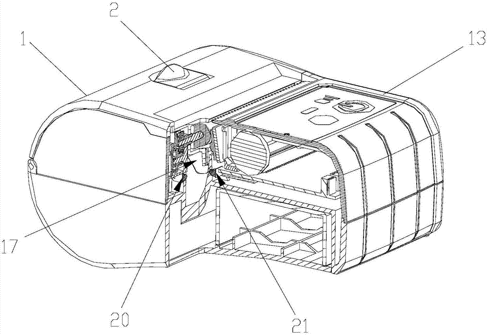
[0016] see figure 1 and 2 , the embodiment of the present invention is provided with a paper compartment cover 1, a casing upper cover 4, a paper compartment partition 5, a thermal printer core 6, a main board 7, a key board 8, a casing lower cover 9, a lithium battery 11, and a battery cover 12. The key panel 13 and the reflective lens 17; the upper cover 4 of the casing is connected with the cover 1 of the paper warehouse through the convex point rotating shaft, the partition plate 5 of the paper warehouse and the lower cover 9 of the casing are assembled with ribs and lines, and the upper cover 4 of the casing It is connected with the casing lower cover 9 through the casing upper cover screw 3 and the casing lower cover screw 10. After the thermal printer core 6 is stacked with the main board 7, it is locked on the casing lower cover 9 by the lowe...


PUM


Abstract

The invention provides an infrared positioning device for heat-sensitive label printing paper and relates to heat-sensitive printers. The infrared positioning device is provided with a paper bin cover, an upper case cover, a lower case cover, a paper bin partition plate, a printer core, a main board, a button board, a lithium battery, a battery cover, a button panel and a reflecting mirror. The upper case cover is connected with the paper bin cover. The paper bin partition plate is linearly assembled to the lower case cover through ribs. The heat-sensitive printer core is stacked on the main board and then locked and fixed to the lower case cover through lower screws of the button board. The heat-sensitive printer core is connected with the main board through flexible printed circuits (FPC). A paper bin cover dial button is arranged on the paper bin cover and is in buckled connection with the paper bin cover. The button board and the upper case cover are locked and fixed through upper screws of the button board. The button board is connected with the main board through flexible flat circuits (FFC). The lithium battery is in buckled connection with the lower case cover and is connected with the main board. The battery cover is arranged on the lithium battery. The button panel is bonded to the upper case cover. The reflecting mirror is bonded to the paper bin cover. An infrared emitting lamp and an infrared receiving lamp are connected with the main board through FPCs and fixed to the lower case cover.

Description

technical field [0001] The invention relates to a thermal printer, in particular to an infrared positioning device for thermal label printing paper. Background technique [0002] The paper positioning infrared device used in the existing thermal printer generally installs the transmitting signal lamp on the cover of the paper compartment. After the cover of the paper compartment is closed, the infrared transmitting lamp and the receiving lamp are in the same axial position. [0003] When the paper compartment cover is opened, the infrared emitting signal lamp rotates and displaces with the opening shaft of the paper compartment cover, and the transmitting signal light is connected with the main board PCBA through the position of the rotation axis of the paper compartment cover through the flexible cable FPC. [0004] When the cover of the paper compartment is closed, the position of the infrared signal lights is on the same axis. (There are roll paper and stack paper in the ...

Claims


Application Information

Patent Timeline
Patent Type & Authority Applications(China)
IPC IPC(8): B41J11/00G01B11/00
CPCG01B11/00B41J11/0095
Inventor 王友爱张添林
Owner XIAMEN JRP ELECTRONICS & TECH
Learn More