Prestress steel purlin-concrete combined continuous rigid frame bridge and construction method thereof

A technology of prestressed steel and rigid frame bridges, applied in bridges, bridge parts, bridge materials, etc., can solve the problems of concrete shrinkage, creep and prestress loss difficult to grasp, unstable concrete material properties, and excessive long-term deflection. , to achieve the effect of easy control of construction links and quality, reliable long-term structural performance, and shortened construction period

Inactive Publication Date: 2010-02-10
CHONGQING JIAOTONG UNIVERSITY
View PDF0 Cites 20 Cited by
  • Summary
  • Abstract
  • Description
  • Claims
  • Application Information

AI Technical Summary

Problems solved by technology

[0004] However, conventional concrete continuous rigid frame bridges have many shortcomings that are difficult to overcome, mainly in the following aspects: with the increase of bridge span, the self-weight of the main girder increases significantly, which greatly limits the development of concrete continuous rigid frame bridges to bridges with larger spans. Possibility: long construction period, many construction links, unstable concrete material properties and unavoidable construction deviation of bending prestressed long beams, resulting in difficult to grasp the shrinkage, creep and prestress loss of concrete in the later stage, making the ideal state of bridge design and its completion There are obvious deviations in the actual state behind the bridge, which is prone to structural cracks and long-term excessive deflection and other diseases;

Method used


Image

  • Prestress steel purlin-concrete combined continuous rigid frame bridge and construction method thereof
  • Prestress steel purlin-concrete combined continuous rigid frame bridge and construction method thereof
  • Prestress steel purlin-concrete combined continuous rigid frame bridge and construction method thereof

Examples


Embodiment Construction

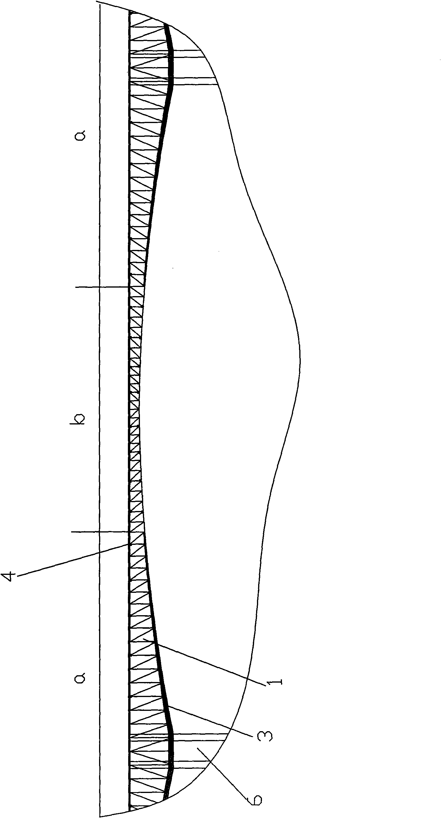
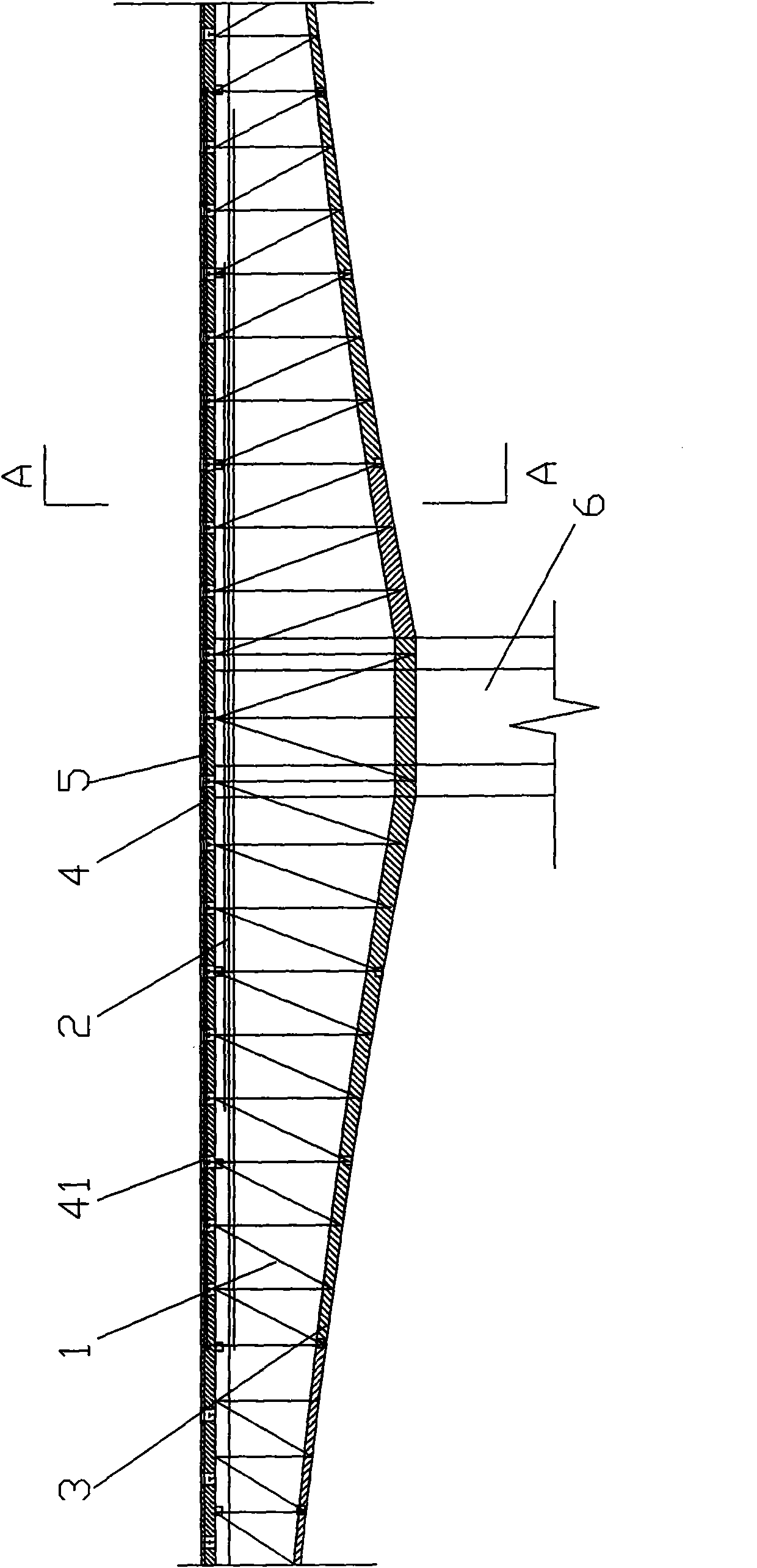
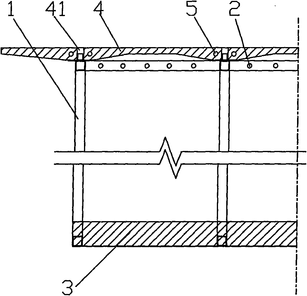
[0036] figure 1 It is a structural schematic diagram of the main girder of the bridge of the present invention, figure 2 Schematic diagram of the section of the main girder bearing negative bending moment, image 3 for figure 2 Sectional view along A-A direction, Figure 4 Schematic diagram of the section of the main beam bearing positive bending moment, Figure 5 for Figure 4 The cross-sectional view along the B-B direction shows that the prestressed steel truss-concrete composite continuous rigid frame bridge of this embodiment includes a main girder. The distance between the bars is provided with horizontal connections and diagonal braces; the top surface of each steel truss beam 1 is fixedly connected with the longitudinal steel plate to form the upper wing steel plate, and the bottom surface of all steel truss beams 1 is fixedly connected with steel plates to form the overall lower wing steel plate;

[0037] In the section of the main girder close to the pier 6 th...


PUM


Abstract

The invention discloses a prestress steel purlin-concrete combined continuous rigid frame bridge and construction method thereof. A steel purlin concrete combined structure with upper and lower swingplates is adopted, girder subsection adopts different combined interfaces according to stress demand of bridge under each construction stage and operating condition, set in vitro and vivo prestress beams are timely applied in batch, and material advantages of the two are fully played; compared with the existing prestress concrete continuous rigid frame bridge, self weight of the girder is greatlyreduced, spanning capacity is obviously increased, and sub structural engineering quantity and bearing capacity requirement of foundation soil are correspondingly reduced. The invention adopts prefabricated concrete bridge road plate for splice, and the prefabricated concrete bridge road plate is joined with the steel truss girder, thus stress is clear and performance is reliable; construction isobviously simplified, quality of each parts is easy to control and check, and disease hidden troubles that the conventional prestress concrete continuous rigid frame bridge is not reliable in curve prestress long strand performance, concrete is cracked in tension and deflection is excessive for a long time caused by contraction creep are avoided.

Description

technical field [0001] The invention belongs to the field of bridge road engineering, in particular to a prestressed steel truss-concrete combined continuous rigid frame bridge and a construction method. Background technique [0002] With the rapid development of my country's national economy and modern transportation, the construction of long-span bridges is increasing, and the requirements for driving comfort are also getting higher and higher. The prestressed concrete continuous rigid frame bridge meets the "safety, practicality and economy" of bridge design in my country. It is one of the widely used reasonable structural forms of long-span bridges. [0003] The continuous rigid frame bridge is developed on the basis of T-shaped rigid frame and continuous girder bridge construction technologies. Both belong to the beam bridge system. Its structure is simple and it has good adaptability to V-shaped valleys. Bending member, the main girder body is continuous, and the girde...

Claims


Application Information

Patent Timeline
Patent Type & Authority Applications(China)
IPC IPC(8): E01D2/00E01D21/00E01D21/10E01D19/12E01D101/28E01D101/30
Inventor 周志祥
Owner CHONGQING JIAOTONG UNIVERSITY
Why Eureka
Try Eureka