Crane with reaction wheel travelling trolley and equalizing end beams

A technology for running trolleys and cranes, which is applied in the directions of traveling bridge cranes, cranes, and traveling mechanisms, can solve the problems of inability to directly hand over goods, waste of manpower and material resources, and inconvenience in the next workshop, and achieve convenient installation, cost saving, and installation reduction. high effect

Inactive Publication Date: 2017-11-17
卢统华
View PDF0 Cites 3 Cited by
  • Summary
  • Abstract
  • Description
  • Claims
  • Application Information

AI Technical Summary

Problems solved by technology

[0002] Existing bridge cranes are used in enterprise workshops. Some workshops are equipped with many machine tools for processing and production. Products and raw materials need to be transported to the next workshop or other departments in real time; the hooks of the cranes in the workshop are hung from the trolley. For hoisting goods, the trolley can only run back and forth along the double girders of the crane, and the crane can only run back and forth along the cart rails on the cross columns on both sides of the workshop, so that the range of goods that the crane hook can lift is within the distance between the two cart rails in the workshop. Within the plane surrounded by the two ends, when the goods at the edge of the plane need to be hoisted, the hook will be pulled obliquely, and the items farther away from this plane (such as o

Method used


Image

  • Crane with reaction wheel travelling trolley and equalizing end beams
  • Crane with reaction wheel travelling trolley and equalizing end beams
  • Crane with reaction wheel travelling trolley and equalizing end beams

Examples


Embodiment approach

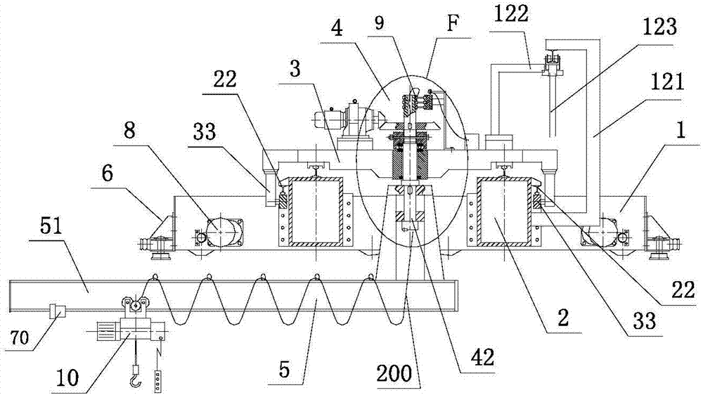
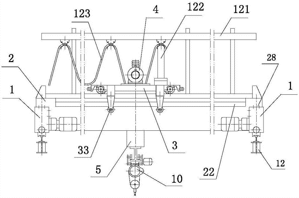
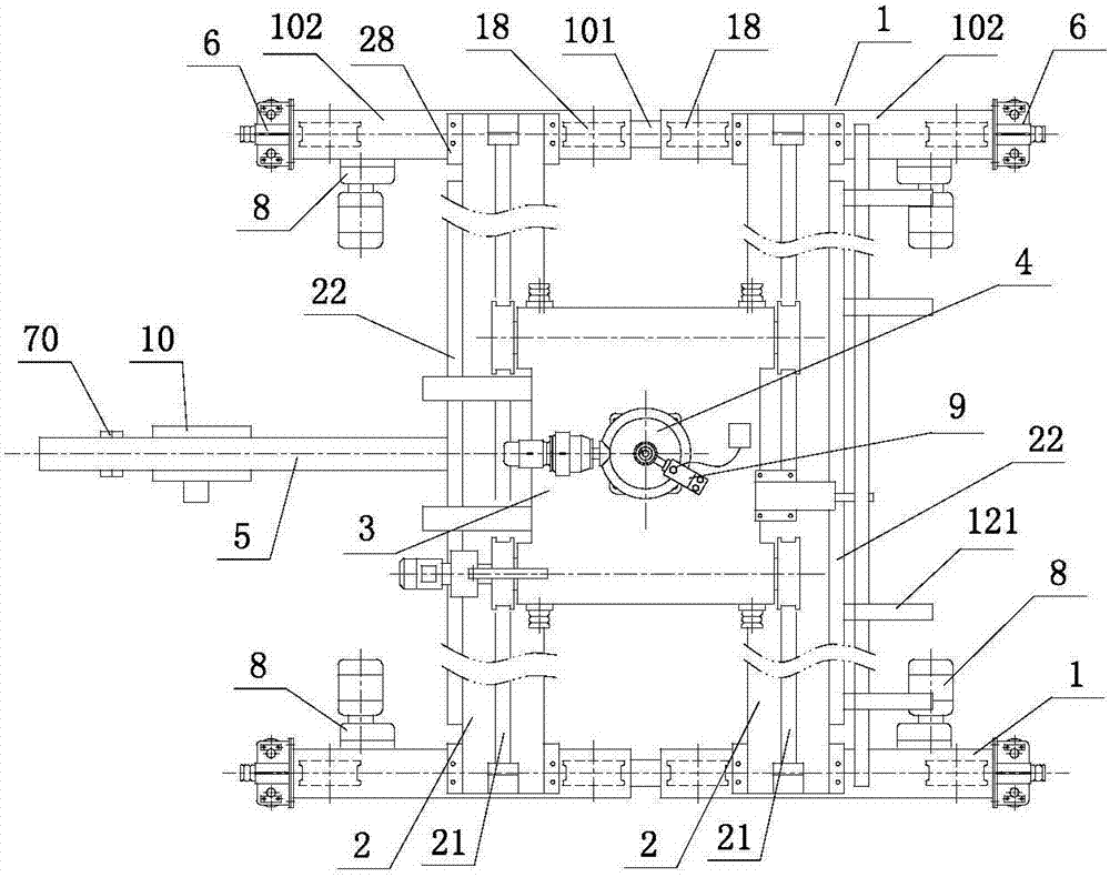
[0042] like figure 1 , figure 2 , image 3 As shown, a crane with an anti-roller running trolley and a balancing end beam includes a double-girder bridge 28; the double-girder bridge includes two end beams 1 and two main beams 2; A rack 121, a movable hanging cable 123 is arranged on the power pick-up rack; a rail 21 is arranged above the two main beams, and the running trolley 3 is connected to the rail; the end beam 1 is composed of two balance end beams 102 and the middle A connecting rod 101 is connected; one end of the balance end beam 102 is connected to the cart drive device 8 with connected axle wheels, and the other end is connected to the passive wheel group 18 with connected axle wheels; the two ends of the end beam 1 are connected to a A set of horizontal wheel devices 6; the outer sides of the two main beams are provided with steel rails 22; both sides of the above-mentioned running trolley 3 are connected with anti-roller devices 33, which are hooked and run o...


PUM


Abstract

The application discloses a crane with a running trolley and a balanced end girder, which includes a double-girder bridge frame with two end girders and two main girders; The running trolley is connected on the track; the end beam is composed of a balanced end beam and a connecting rod; one end of the balanced end beam is connected to the driving device of the cart, and the other end is connected to the passive wheel group; both ends of the end beam are connected to the horizontal wheel device; the outer side of the main beam is equipped with rails; Both sides of the trolley are connected with anti-roller devices, and the anti-roller devices are hooked and run on the rails; the two driving wheels on the trolley are connected to the same driving axle to drive; the trolley is equipped with a rotating mechanism; the lower end of the boom shaft and the cantilever member Connection, the upper end is connected to the collector slip ring; the electric hoist is installed on the cantilever member; the car stop device is connected to the cantilever beam; the cantilever beam is located under the main beam and can rotate at any angle on the horizontal plane.

Description

technical field [0001] The present application relates to the field of cranes, and in particular, to a crane with a running trolley with reverse rollers and a balancing end beam. Background technique [0002] Existing bridge cranes are used in enterprise workshops. In some workshops, many machine tools are arranged for processing and production. Products and raw materials need to be transported to the next workshop or other departments in real time; the hooks of the cranes in the workshop are hung from the trolley. For hoisting goods, the trolley can only run back and forth along the double beams of the crane, and the crane can only run back and forth along the cart tracks on the span columns on both sides of the workshop, so that the range of goods that can be hoisted by the crane hook is within the two cart tracks of the workshop. Within the plane enclosed by the two ends, when the goods on the edge of this plane need to be hoisted, the hook will be pulled diagonally, and ...

Claims


Application Information

Patent Timeline
IPC IPC(8): B66C17/04B66C11/10B66C9/14B66C9/08B66C9/16B66C6/00B66C7/16B66C23/84B66C13/12
CPCB66C17/04B66C6/00B66C7/16B66C9/08B66C9/14B66C9/16B66C11/10B66C13/12B66C23/84B66C2700/0342B66C2700/035
Inventor 卢统华
Owner 卢统华
Why Eureka
Try Eureka