
Dehumidifying power balancer

A balancer and power technology, applied in instruments, humidity control, non-electric variable control, etc., can solve the problems of not easy to dissipate heat, affect the service life of the power balancer, and the power balancer is easily affected by humidity, so as to extend the service life, Guarantee the effect of stable operation

Inactive Publication Date: 2017-11-17
广西邦世电气有限公司
View PDF3 Cites 0 Cited by
  • Summary
  • Abstract
  • Description
  • Claims
  • Application Information

AI Technical Summary

Problems solved by technology

[0003] The purpose of this invention is to provide a dehumidification power balancer. The technical problem to be solved is: in the space of the cabinet, it is not easy to dissipate heat, which seriously affects the service life of the power balancer, and the power balancer is easily affected by humidity.

Method used


Image

  • Dehumidifying power balancer
  • Dehumidifying power balancer

Examples


Embodiment Construction

[0012] The principles and features of the present invention are described below in conjunction with the accompanying drawings, and the examples given are only used to explain the present invention, and are not intended to limit the scope of the present invention.

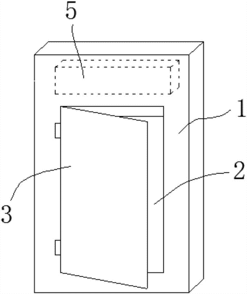
[0013] like figure 1 and figure 2 As shown, a dehumidification power balancer includes a cabinet body 1, a power balancer body 2, an electric door 3 and a temperature and humidity relay 4, the electric door 3 is placed on the cabinet body 1, and is connected to the cabinet body 1 Hinge connection; the power balancer body 2 is placed in the cabinet 1; the input end of the temperature and humidity relay 4 is connected to the power supply through a line; the output end of the temperature and humidity relay 4 is connected to the electric door 3 connected by wire;

[0014] An electric heater 5 is arranged on the inside top of the cabinet body 1, and the electric heater 5 is connected to the output end of the temperatu...


PUM


Abstract

The invention relates to a dehumidifying power balancer, which comprises a cabinet body, a power balancer body, an electrically-operated gate and a temperature and humidity relay. The electrically-operated gate is arranged on the cabinet body, and is in hinge connection with the cabinet body; the power balancer body is arranged in the cabinet body; the input end of the temperature and humidity relay is connected with a power supply through a line; the output end of the temperature and humidity relay is connected with the electrically-operated gate through a line; the inner top portion of the cabinet body is provided with an electric heater; an air outlet of the electric heater faces to the power balancer body; and the electric heater is connected with the output end of the temperature and humidity relay through a line. Compared with the prior art, the dehumidifying power balancer can effectively maintain the temperature in the cabinet body, ensures smooth operation of the power balancer body and prolongs the service life thereof.

Description

technical field [0001] The invention relates to the technical field of power balancers, in particular to a dehumidification power balancer. Background technique [0002] In the existing technical solutions, the power balancer generates a large amount of heat, which is not easy to dissipate heat in the space of the cabinet, which seriously affects the service life of the power balancer. At the same time, the power balancer is easily affected by dust; and the power balancer is easily affected by humidity. ; So it is necessary to solve this problem. Contents of the invention [0003] The purpose of the present invention is to provide a dehumidification power balancer. The technical problem to be solved is: in the space of the cabinet body, it is not easy to dissipate heat, which seriously affects the service life of the power balancer, and the power balancer is easily affected by humidity. [0004] The technical solution of the present invention to solve the above-mentioned ...

Claims


Application Information

Patent Timeline
Patent Type & Authority Applications(China)
IPC IPC(8): G05D22/02
CPCG05D22/02
Inventor 张宇文陆辉李伟恒黄龄格黄益华
Owner 广西邦世电气有限公司
Learn More