
A Low Temperature Cooling System for High Temperature Superconducting Motor Rotor Using Liquid Hydrogen

A motor rotor and high-temperature superconducting technology, which is applied in superconducting magnets/coils, cooling/ventilation devices, superconducting elements, etc., can solve problems such as the inability to use superconducting motor rotors, the inability to meet the temperature of 30K, and the high cost of helium pumps , to achieve the effect of increased reliability, reduced cost and low working pressure

Active Publication Date: 2022-05-27
CHINA SHIP SCIENTIFIC RESEARCH CENTER (THE 702 INSTITUTE OF CHINA SHIPBUILDING INDUSTRY CORPORATION)
View PDF6 Cites 0 Cited by
  • Summary
  • Abstract
  • Description
  • Claims
  • Application Information

AI Technical Summary

Problems solved by technology

However, due to the heat leakage of the cryogenic container itself and the conduction heat of the current lead, it is necessary to continuously replenish liquid nitrogen, and the working temperature of the magnet is around 70K, which cannot meet the requirement of 30K temperature.
[0005] 2. Direct conduction cooling of superconducting magnets through cryogenic refrigerators. This method is simple and direct, but it cannot be applied to rotating superconducting motor rotors, especially when the linear velocity is high.
[0006] 3. Adopt cold helium forced convection method. This method uses cold helium as the intermediate cooling medium and uses helium pump as the circulation power. However, the operating pressure of this method is high and the system is complex, and the cost of the helium pump is relatively high.

Method used


Image

  • A Low Temperature Cooling System for High Temperature Superconducting Motor Rotor Using Liquid Hydrogen
  • A Low Temperature Cooling System for High Temperature Superconducting Motor Rotor Using Liquid Hydrogen

Examples


Embodiment Construction

[0026] The specific embodiments of the present invention will be further described below with reference to the accompanying drawings.

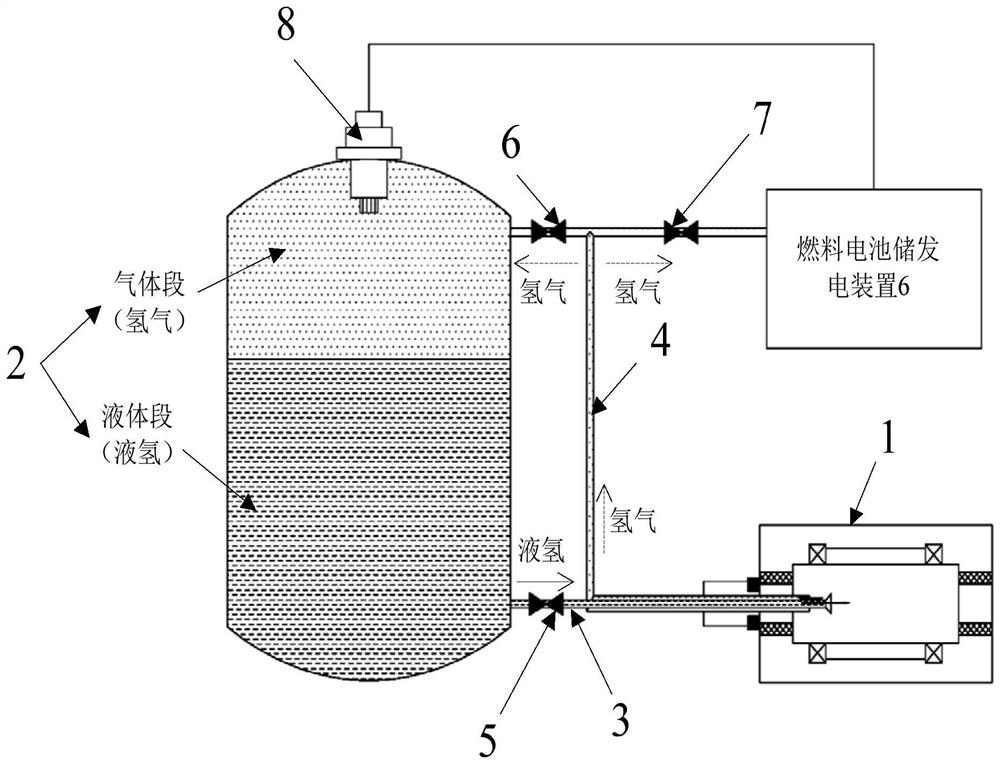
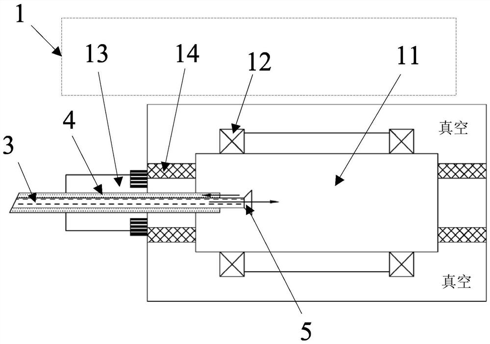
[0027] This application discloses a low-temperature cooling system for a high-temperature superconducting motor rotor using liquid hydrogen. Please refer to figure 1 The system block diagram shown and figure 2 As shown in the partial structure diagram, the system includes a thermal superconducting motor rotor 1, a liquid hydrogen storage tank 2, a liquid hydrogen delivery pipe 3 and a hydrogen delivery pipeline 4. Wherein, liquid hydrogen is stored in the liquid hydrogen storage tank 2, and the liquid hydrogen is the low-temperature cooling medium used for the motor rotor in this application. The liquid hydrogen storage tank 2 forms a liquid section at the bottom and a gas section at the top, and the liquid section is Liquid hydrogen, the gas segment is hydrogen, such as figure 1 shown. The liquid hydrogen storage tank 2 is a multi-layer s...


PUM


Abstract

The invention discloses a high-temperature superconducting motor rotor low-temperature cooling system using liquid hydrogen, and relates to the field of low-temperature technology for superconducting applications. In the system, liquid hydrogen is stored in a liquid hydrogen storage tank to form a liquid section at the bottom and a gas section at the top. , the liquid hydrogen in the liquid section is transferred to the liquid hydrogen gasification chamber in the outer wall cavity of the high temperature superconducting motor rotor under the action of gravity through the liquid hydrogen delivery pipe for heat exchange to achieve cooling, and the hydrogen gas formed after the liquid hydrogen gasification passes through the hydrogen gas The gas section of the delivery pipeline that is transported back to the liquid hydrogen storage tank maintains the pressure in the liquid hydrogen storage tank, thus forming a closed cycle. The system uses liquid hydrogen as a low-temperature cooling medium, which can effectively maintain the temperature in the liquid hydrogen gasification chamber to meet the The working temperature of the superconducting magnet is required, and it is driven by gravity, so there is no need to use an additional circulation pump, which improves the reliability of the system.

Description

technical field [0001] The invention relates to the low-temperature technical field of superconducting applications, in particular to a low-temperature cooling system for a high-temperature superconducting motor rotor using liquid hydrogen. Background technique [0002] Since the discovery of high-temperature superconducting materials in 1986, high-temperature superconducting materials have developed rapidly and have caused the tracking development of many countries in the world. The development and application of superconducting wires are becoming more and more extensive, such as superconducting current limiters, superconducting cables. , superconducting machines, superconducting magnetic energy storage, etc. At present, the commercialized high-temperature superconducting wires mainly include the first-generation Bi-series high-temperature superconducting wires and the second-generation Yi-series high-temperature superconducting wires. The working temperature of the superc...

Claims


Application Information

Patent Timeline
Patent Type & Authority Patents(China)
IPC IPC(8): H01F6/04H02K9/20H02K9/24H02K55/00
CPCH01F6/04H02K9/20H02K9/24H02K55/00Y02E40/60
Inventor 张哲李斌闵婕陈伟政
Owner CHINA SHIP SCIENTIFIC RESEARCH CENTER (THE 702 INSTITUTE OF CHINA SHIPBUILDING INDUSTRY CORPORATION)
Learn More