
A photovoltaic roof unit and laying method

A photovoltaic and photovoltaic tile technology, which is applied in photovoltaic power stations, photovoltaic power generation, photovoltaic modules, etc., can solve the problems of photovoltaic module blocking, module aging, debris accumulation, etc., and achieve the effect of avoiding loss and prolonging the service life

Active Publication Date: 2022-04-08
BAODING JIASHENG PHOTOVOLTAIC TECH
View PDF7 Cites 0 Cited by
  • Summary
  • Abstract
  • Description
  • Claims
  • Application Information

AI Technical Summary

Problems solved by technology

[0003] The photovoltaic modules are embedded in the supporting structure, so that the solar panels and building materials are integrated, directly applied to the roof, and installed on the roof structure like ordinary roof tiles. This is the photovoltaic tile. The structure of the existing photovoltaic tile roof unit follows the traditional The roof tile structure, that is, layer by layer laying, this laying method is likely to cause the second layer of photovoltaic tiles to partially block the first layer of photovoltaic tiles, and it is easy to cause some photovoltaic modules to be in a large section due to the angle of the sun. The time setting cannot be in direct contact with sunlight, resulting in partial waste of photovoltaic modules. The photovoltaic tiles in another type of photovoltaic tile roof unit have one end on the top and one end on the bottom, forming a slope. Although the problem of shading is avoided, due to the up and down The two layers of photovoltaic tiles are not on the same level, which is easy to cause the accumulation of debris, and finally some photovoltaic modules are blocked, which affects the power generation efficiency. Moreover, when the traditional photovoltaic tile roof generates electricity in summer, because the photovoltaic modules absorb solar energy for conversion, It will generate a lot of heat, and it will be in a high temperature environment for a long time, which greatly affects the life of the photovoltaic module. Moreover, because the photovoltaic tile roof unit is completely covered on the roof, the indoor temperature is much higher than that when the photovoltaic tile roof unit is not installed. In areas with low temperature, if the snow and ice on the photovoltaic tile roof unit cannot be cleaned in time, it is easy to cause the components to become old after a long time, and the power generation work cannot be completed

Method used


Image

  • A photovoltaic roof unit and laying method
  • A photovoltaic roof unit and laying method
  • A photovoltaic roof unit and laying method

Examples


Embodiment Construction

[0091] The preferred embodiments of the present invention are given below in conjunction with the accompanying drawings to describe the technical solution of the present invention in detail, but the present invention is not limited to the scope of the described embodiments.

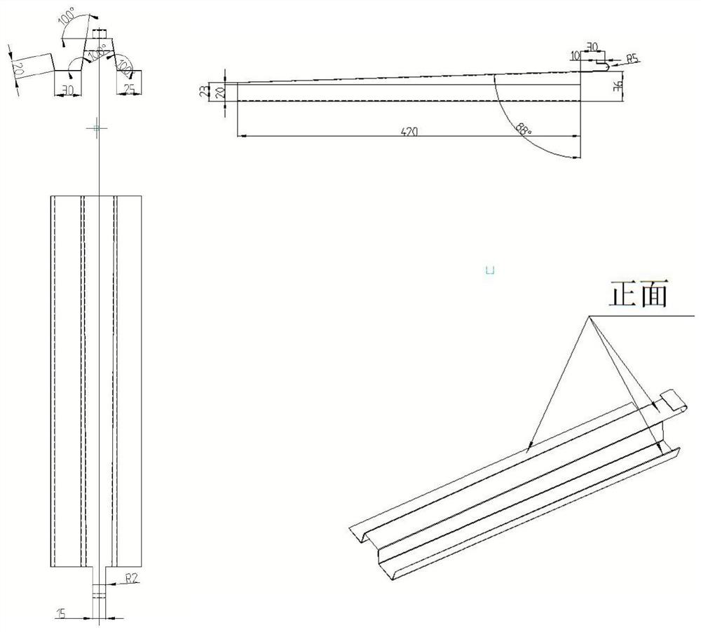
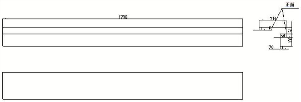
[0092] Such as Figure 1-18 As shown, this embodiment provides a photovoltaic roof unit, such as Figure 2-13 As shown, including: several groups of photovoltaic tile units, basic frame units, among which, such as Figure 18 As shown, each group of photovoltaic tile units includes several pieces of photovoltaic tiles, and the photovoltaic tiles are photovoltaic flat tiles, which are arranged on the basic frame unit; The second bottom plate, the third bottom plate of photovoltaic tiles;

[0093] The photovoltaic tile bottom plate 2 is arranged on both ends and the middle of the bottom surface of the photovoltaic tile, and is used for connecting the photovoltaic tile to the basic frame unit; each photovol...


PUM


Abstract

The invention discloses a photovoltaic roof unit, which includes several groups of photovoltaic tile units and a basic frame unit, wherein each group of photovoltaic tile units includes a photovoltaic flat tile and a photovoltaic tile bottom plate, and the basic frame unit includes a basic frame structure A unit and a photovoltaic tile auxiliary unit arranged on the basic frame structure; a method for laying a photovoltaic roof unit, laying a basic frame structure unit on a target roof, laying a photovoltaic tile auxiliary unit on the structural unit, and finally laying a photovoltaic tile unit , all the photovoltaic flat tiles of the present invention are on the same level, and a thermal cycle system is designed between the photovoltaic tile unit and the basic frame unit, so that the entire photovoltaic roof unit works at the same relatively safe temperature, greatly extending the It improves its service life and avoids the loss caused by long-term high temperature or low temperature, and provides an effective solution for the application of the photovoltaic roof unit under extreme conditions.

Description

technical field [0001] The invention belongs to the field of photovoltaic power generation, and in particular relates to a photovoltaic roof unit and a laying method. Background technique [0002] It is not uncommon to install solar photovoltaic panels on the roof to generate electricity, but the roofs of these farmers do not have any obtrusive power generation equipment except for the tiles, and the power generation far exceeds that of ordinary houses; it is not difficult to install solar panels to burn some bath water, but these farmers All power consumption such as air conditioners, refrigerators, and electric lights is expected to be self-sufficient. You have to ask, what to do on rainy days, and where does the sun come from at night when electricity consumption is at its peak? Is it possible that each of these farmers has installed a huge battery in their home to store the electricity generated by the solar energy? However, large batteries not only pose hidden dangers ...

Claims


Application Information

Patent Timeline
Patent Type & Authority Patents(China)
IPC IPC(8): E04D13/18E04D3/36H02S10/00H02S20/25H02S40/42H02S40/44F24S50/40F24S10/90
CPCE04D13/00E04D3/3601H02S20/25H02S40/42H02S40/425H02S40/44H02S10/00F24S50/40F24S10/90Y02E10/44Y02E10/50Y02E10/60Y02B10/10Y02B10/20Y02B10/70
Inventor 代松周海亮苏红月陈敬欣
Owner BAODING JIASHENG PHOTOVOLTAIC TECH
Learn More