Cooling device for electrical mechanical equipment assembling

A technology of electrical machinery and cooling devices, which is applied in the structural parts of electrical equipment, electrical components, cooling/ventilation/heating transformation, etc., and can solve problems such as poor heat dissipation performance of protection boxes, burnout of electrical mechanical equipment, and affecting operating conditions. To achieve the effect of improving heat dissipation, improving stability and facilitating maintenance

Inactive Publication Date: 2017-11-17
曾林浩
View PDF0 Cites 1 Cited by
  • Summary
  • Abstract
  • Description
  • Claims
  • Application Information

AI Technical Summary

Problems solved by technology

[0002] In the construction of engineering projects, the operation and operation of electrical machinery equipment is installed in the protective box, and operators can control the operation status of electrical machinery equipment in real time. Since electrical machinery equipment will generate a lot of heat during operation, the existing The heat dissipation performance of the protection box is poor, which seriously affects its operation status
Operating in a high-temperature environment, once the operator is difficult to find out in time or the temperature is not cooled in time, it will lead to burnout of electrical machinery and equipment, resulting in serious production losses

Method used


Image

  • Cooling device for electrical mechanical equipment assembling
  • Cooling device for electrical mechanical equipment assembling

Examples


Embodiment Construction

[0020] The following will clearly and completely describe the technical solutions in the embodiments of the present invention with reference to the accompanying drawings in the embodiments of the present invention. Obviously, the described embodiments are only some, not all, embodiments of the present invention. Based on the embodiments of the present invention, all other embodiments obtained by persons of ordinary skill in the art without making creative efforts belong to the protection scope of the present invention.

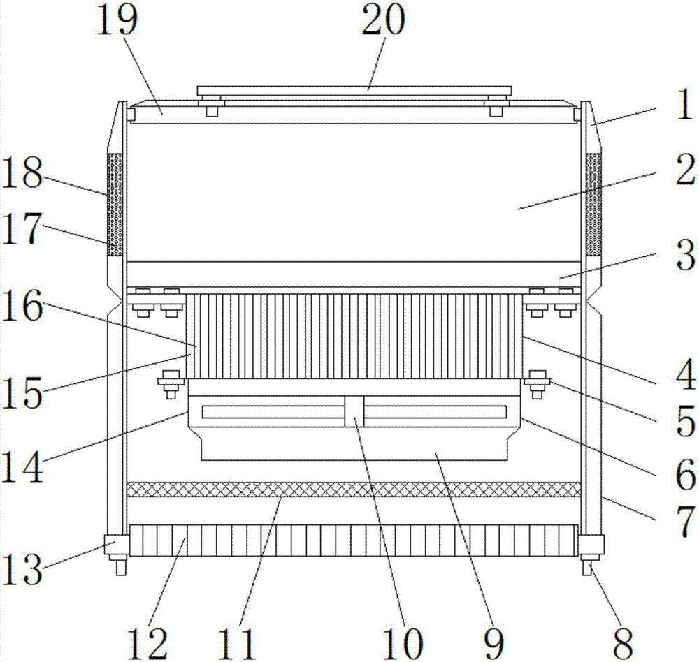
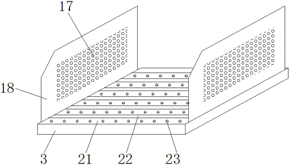
[0021] see Figure 1~2 , in an embodiment of the present invention, a cooling device for assembling electric mechanical equipment, including an equipment box 1, a radiator 4, a heat dissipation fan 6 and a heat dissipation chassis 7, the equipment box 1 is installed on the top of the heat dissipation chassis 7, and the equipment The box 1 is composed of a base 3, side baffles 18 and a top plate 19. The base 3 is welded between the equipment box 1 and the heat ...


PUM


Abstract

The invention discloses a cooling device for electric mechanical equipment assembly, which comprises an equipment box, a radiator, a cooling fan and a cooling box, the equipment box is installed on the top of the cooling box, and the equipment box consists of a base, a side baffle and a top The base is composed of a number of parallel and equally spaced support plates, and a number of fixing screws are threaded on the support plate, and the bottom ends of the fixing screws are connected to the heat exchange fins inside the radiator, and a number of The heat exchange fins are distributed in parallel, the heat exchange fins are provided with circulation grooves, and the top of the circulation grooves is connected with the ventilation grooves; the side baffles are provided with a number of air inlet holes; the heat exchange between the base and the radiator is improved. The thermal effect and the heat dissipation effect of the radiator; the rotation of the fan blade is convenient to extract the air in the assembly room through the ventilation slot and the circulation slot, and the external air is replenished into the assembly room from the air inlet in time, which can effectively cool down the electrical mechanical equipment in the assembly room and improve the power consumption. The stability of mechanical equipment operation.

Description

technical field [0001] The invention relates to the technical field of electrical equipment, in particular to a cooling device for assembling electrical mechanical equipment. Background technique [0002] In the construction of engineering projects, the operation and operation of electrical machinery equipment is installed in the protective box, and operators can control the operation status of electrical machinery equipment in real time. Since electrical machinery equipment will generate a lot of heat during operation, the existing The heat dissipation performance of the protection box is poor, which seriously affects its operation status. Operating in a high-temperature environment, once the operator is difficult to find out in time or the cooling process is not timely, it will lead to burnout of electrical machinery and equipment, resulting in serious production losses. Therefore, there is a need for a convenient assembly of electric mechanical equipment to a cooling dev...

Claims


Application Information

Patent Timeline
Patent Type & Authority Applications(China)
IPC IPC(8): H05K7/20
CPCH05K7/20145H05K7/20172H05K7/20418
Inventor 曾林浩
Owner 曾林浩
Why Eureka
Try Eureka