Diaphragm system used for ophthalmological equipment and ophthalmological equipment

A diaphragm and equipment technology, applied in the field of ophthalmology equipment, can solve the problems that the light spot cannot be collected, the optometry is inaccurate, and the position of the light spot deviates, etc.

Pending Publication Date: 2017-11-21
SUZHOU SIHAITONG INSTR
View PDF10 Cites 3 Cited by
  • Summary
  • Abstract
  • Description
  • Claims
  • Application Information

AI Technical Summary

Problems solved by technology

However, in the actual measurement, the subject’s eyeballs cannot be fixed to keep the eyeballs at the same position during the measurement process, so the spot position will deviate in the collected images, and even some spots cannot be collected. lead to inaccurate optometry

Method used


Image

  • Diaphragm system used for ophthalmological equipment and ophthalmological equipment
  • Diaphragm system used for ophthalmological equipment and ophthalmological equipment
  • Diaphragm system used for ophthalmological equipment and ophthalmological equipment

Examples


Embodiment 1

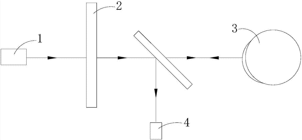
[0030] This embodiment provides an optometry instrument, specifically a programmable LCD diaphragm system of the optometry instrument. Refer to attached figure 1 As shown, a programmable LCD aperture system, including:

[0031] The light source, specifically an infrared light source, is used to emit infrared light, and the wavelength of the infrared light is 800~950nm;

[0032] A beam generating mechanism having a plurality of light-transmitting regions for splitting infrared light into multiple beams;

[0033] The image collector is used to collect images of multiple light spots formed by multiple beams of infrared light respectively on the subject's retina, specifically a CCD sensor 4;

[0034] The diaphragm system also includes a driving mechanism, which is used to drive the multiple light-transmitting regions to move along a direction perpendicular to the optical axis to change the positions of the multiple light-transmitting regions. The optical axis here refers to the...

Embodiment 2

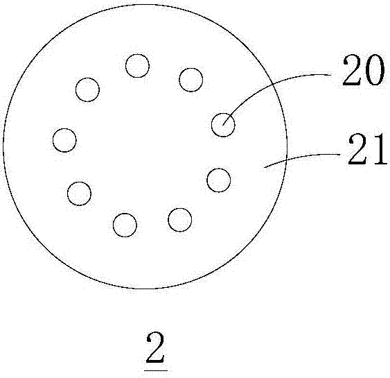
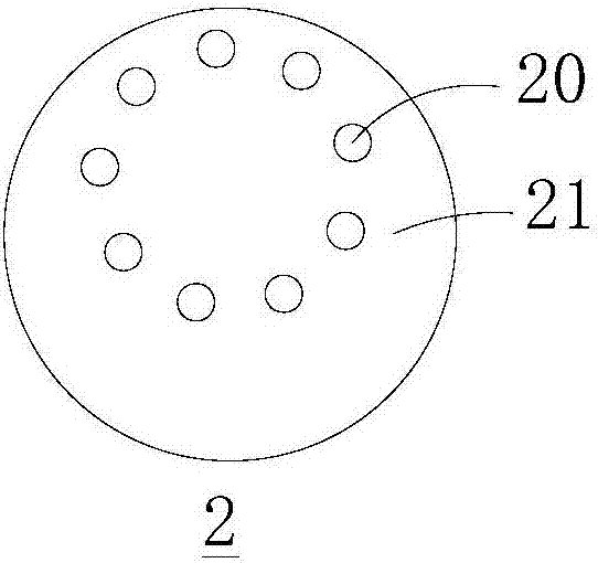
[0038] This embodiment is basically the same as Embodiment 1, and the difference from Embodiment 1 is that the light beam generating mechanism is different.

[0039] Specific as attached Figure 3a and 3b As shown, the light beam generating mechanism is a shading plate 2', and a plurality of light-transmitting holes 20' are opened on the shading plate 2', and the light-transmitting holes 20' are the light-transmitting regions. The infrared light is emitted from the light source 1', and then divided into multiple infrared beams through the multiple light-transmitting holes 20' of the light-shielding plate 2'. The multiple infrared beams enter the human eye 3' and form light spots on the retina, and pass through the CCD sensor 4 'Collect spot image. The shading plate 2' is driven to move by a mechanical mechanism, such as a drive mechanism comprising a motor or a drive cylinder for driving the shading plate 2' to move in a direction perpendicular to the optical axis.

[0040]...


PUM


Abstract

The invention provides ophthalmological equipment and a diaphragm system, and belongs to the field of ophthalmological instrument. The diaphragm system comprises a light source, a light beam generating mechanism, an image collector and a driving mechanism, the light source is used for emitting infrared light, the light beam generating mechanism comprises a plurality of light-penetrating areas and used for separating the infrared light into a plurality of light beams, the image collector is used for collecting images of a plurality of faculae formed by the infrared light beams on a retina of a patient, and the driving mechanism is used for driving the light-penetrating areas to move along a direction perpendicular to an optical axis so as to change positions of the light-penetrating areas. The light beam generating mechanism is an LCD (liquid crystal display) screen which is provided with a plurality of the light-penetrating areas allowing the infrared light to penetrate. The ophthalmological equipment and the diaphragm system have the advantages that even though the position of an eye ball of the patient changes during inspection, at least one detecting position can always exist in the light-penetrating areas, and under the detecting position, the image collector can collect all faculae completely, so that data obtained from fitting are accurate.

Description

technical field [0001] The invention belongs to ophthalmic equipment, in particular to an aperture system for ophthalmic equipment and ophthalmic equipment such as fundus cameras, refractometers, and slit lamps with the aperture system. Background technique [0002] The diaphragm system is one of the core components of ophthalmic equipment such as refractometers. At present, the working principle of the aperture system is: firstly, the light beam is divided into multiple beams by opening multiple holes, and the images of the light spots formed by the multiple beams of light on the retina are collected, wherein the number of holes is at least 7 and Arranged at equal intervals along a circle, correspondingly, there are a corresponding number of light spots in the collected image, and the diopter can be calculated by fitting these multiple light spots. However, in the actual measurement, the subject’s eyeballs cannot be fixed to keep the eyeballs at the same position during th...

Claims


Application Information

Patent Timeline
Patent Type & Authority Applications(China)
IPC IPC(8): A61B3/103A61B3/12A61B3/14A61B3/135
CPCA61B3/0016A61B3/103A61B3/12A61B3/135A61B3/14
Inventor 沈激
Owner SUZHOU SIHAITONG INSTR
Why Eureka
Try Eureka