Eureka AIR delivers breakthrough ideas for toughest innovation challenges, trusted by R&D personnel around the world.

Remote isolation circuit and braking fault isolation system and method for unmanned train

An isolated circuit and unmanned driving technology, which is applied in the direction of brake safety system, general control system, control/regulation system, etc., can solve problems such as false isolation, increased construction costs, hidden dangers of vehicle operation safety, etc., to ensure vehicle safety system The effect of driving distance and driving safety

Active Publication Date: 2017-11-21
CRRC IND INST CO LTD +2
View PDF7 Cites 6 Cited by
  • Summary
  • Abstract
  • Description
  • Claims
  • Application Information

AI Technical Summary

Problems solved by technology

[0004] However, the first isolation method needs to increase the construction cost of emergency maintenance channels, formulate complex emergency operation rules, and increase the difficulty of operation management. At the same time, it needs to rely on people to ensure the safety and reliability of fault handling. The safety of this method itself In the second isolation method, when the network directly sends instructions to the braking unit that needs to be isolated, since the network equipment is considered as a non-safety equipment in rail transit, and its output function is realized by software, this The implementation of the function is also non-safe
When there is a failure in the program operation, or when the IO board has a wrong output when it is disturbed by the outside world, it is very likely that there will be false isolation, or more than one bogie will be isolated, which will cause safety hazards to the vehicle operation.

Method used


Image

  • Remote isolation circuit and braking fault isolation system and method for unmanned train
  • Remote isolation circuit and braking fault isolation system and method for unmanned train
  • Remote isolation circuit and braking fault isolation system and method for unmanned train

Examples


Embodiment Construction

[0046] In order to make the purpose, technical solutions and advantages of the embodiments of the present invention clearer, the technical solutions in the embodiments of the present invention will be clearly and completely described below in conjunction with the drawings in the embodiments of the present invention. Obviously, the described embodiments It is a part of embodiments of the present invention, but not all embodiments. Based on the embodiments of the present invention, all other embodiments obtained by persons of ordinary skill in the art without creative efforts fall within the protection scope of the present invention.

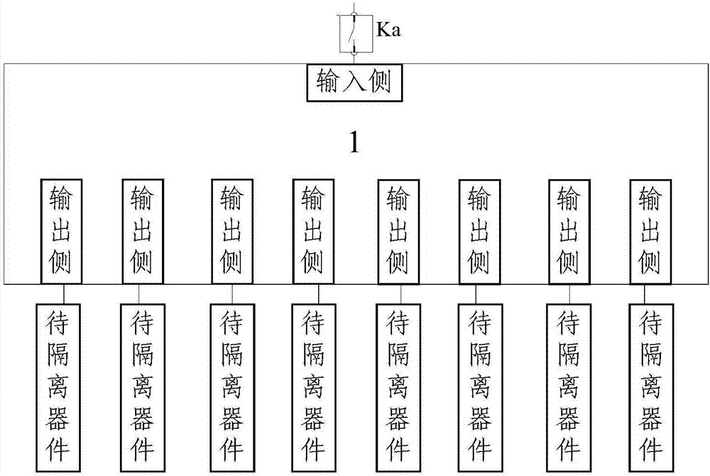
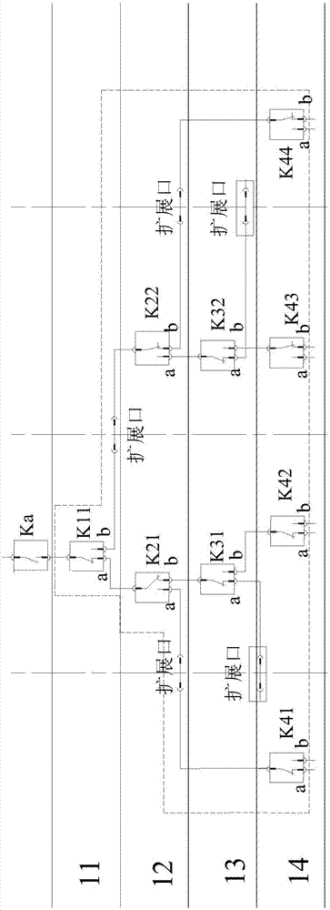
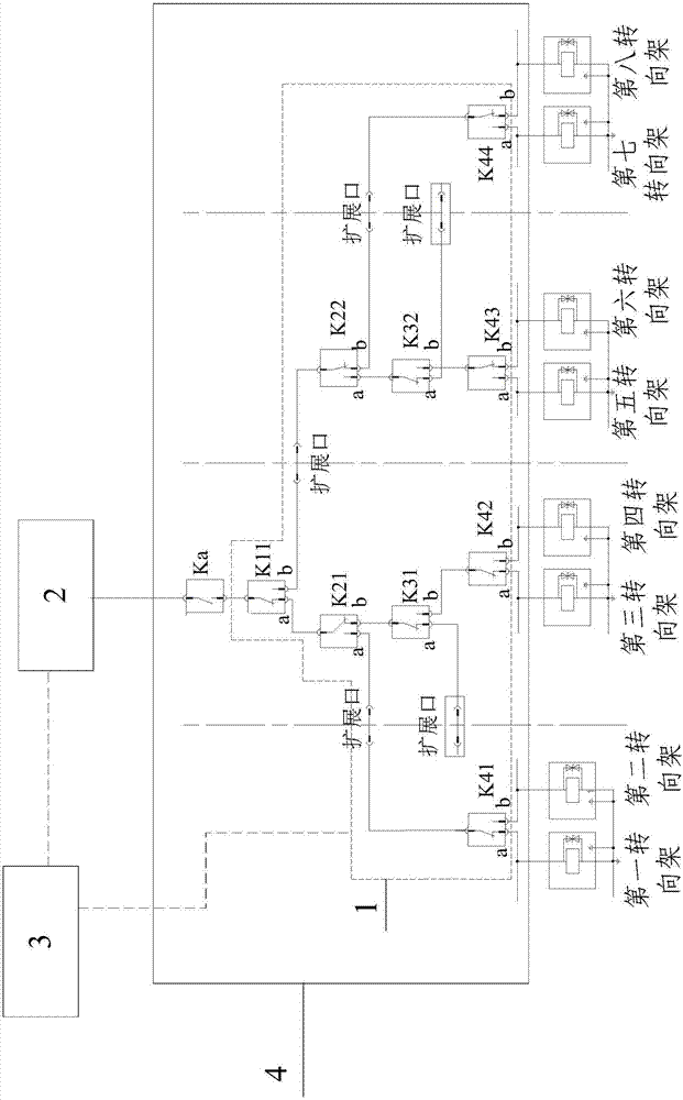
[0047] Embodiment 1 of the present invention provides a specific implementation of a remote isolation circuit, see figure 1 , the remote isolation circuit specifically includes the following content:

[0048] The isolation command control switch Ka, and the one-two path connection control group 1 connected to the isolation command control switch ...


PUM


Abstract

The invention discloses a remote isolation circuit and a braking fault isolation system and method for an unmanned train. The remote isolation circuit comprises an isolation command control switch and an either-or path connection control group connected to the isolation command control switch, wherein the either-or path connection control group comprises an input side and a plurality of output sides; the input side of the either-or path connection control group is connected in series with the isolation command control switch; and each output side of the either-or path connection control group is provided with a connection point so that the output sides of the either-or path connection control group are connected to a device needing to be isolated through the connection points. The remote isolation circuit can accurately and safely realize the remote isolation of the braking fault of a bogie of the unmanned train and meet the safe operation requirement of isolating air brake of only one faulty bogie of the unmanned train, thereby preventing from mistakenly cutting off any bogies or cutting off more than one bogie with braking fault because of a single point of failure in the circuit, and ensuring the safe braking distance and traveling safety of the unmanned train.

Description

technical field [0001] The invention relates to the field of unmanned driving technology, in particular to a remote isolation circuit, a braking fault isolation system and method for an unmanned train. Background technique [0002] With the improvement of users' requirements for the automation of subway vehicles, fully automatic and unmanned subway vehicles have become the mainstream of the current demand for subway vehicles. The unmanned subway puts forward higher requirements for the reliability and availability of the vehicle, especially when there are component or system-level failures that affect the normal operation of the vehicle during vehicle operation, the unmanned vehicle must have corresponding automatic or The remote processing method; the braking failure of the bogie that cannot be relieved is an important level of failure. When the braking of the bogie cannot be relieved, the vehicle must be able to isolate the faulty bogie by air braking. The reliability req...

Claims


Application Information

Patent Timeline
Patent Type & Authority Applications(China)
IPC IPC(8): B61L15/00B60T17/22G05B23/02
CPCG05B23/0275B60T17/228B61L15/0036B61L15/0081
Inventor 翟国锐王子超张文彬张传琪张振英赵洪涛闫一凡刘天赋
Owner CRRC IND INST CO LTD
Why Eureka
Eureka Blog
Learn More