Eureka AIR delivers breakthrough ideas for toughest innovation challenges, trusted by R&D personnel around the world.

Mini-tiller

A cultivator, miniature technology, applied in the direction of tillage machines, agricultural machinery and implements, shovels, etc., can solve the problems of consuming a lot of material resources, manpower and time, poor passability and mobility, and no consideration of driving problems, etc., to achieve simple operation, The effect of reducing material resources and improving performance

Inactive Publication Date: 2013-12-18
湖南长沙果福车业有限公司
View PDF10 Cites 1 Cited by
  • Summary
  • Abstract
  • Description
  • Claims
  • Application Information

AI Technical Summary

Problems solved by technology

[0002] The existing micro-tillers are mainly walk-behind micro-tillers, and the existing defects are: (1) when working, people need to walk upright in the field with the machine, which is labor-intensive and low-efficiency; (2) adopts The structure of the rotary tillage roller and the attached agricultural implements has poor passability and mobility in the mountainous fields; (3) the problem of driving on land is not considered, and it is generally not possible to drive directly from home to the field, and agricultural vehicles are needed It takes a lot of material resources, manpower and time to move the machine, and the use effect is not good, which limits the popularity of tillage machines in rural areas to a certain extent.

Method used


Image

  • Mini-tiller
  • Mini-tiller

Examples


Embodiment Construction

[0020] The present invention will be further described below in conjunction with the accompanying drawings and embodiments.

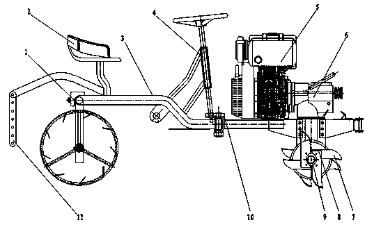
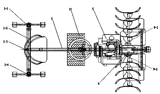
[0021] With reference to accompanying drawing, present embodiment comprises frame 3, and described frame 3 is provided with rear axle 1, seat 2, direction machine 4, engine 5, gearbox 6, and described rear axle 1 includes left bearing sleeve bar 1 -1, crossbeam 1-2, connecting mechanism 1-3, right bearing sleeve rod 1-4, described crossbeam 1-2 is respectively connected with left bearing sleeve rod 1-1, right bearing sleeve rod 1-4 in rotation, and described The connection mechanism 1-3 includes a connecting shaft, a self-lubricating bearing, and a connecting sleeve. The connecting sleeve is welded and fixed on the middle hole of the beam 1-2. One end of the connecting shaft is fixedly connected to the frame 3, and the other end is connected by a self-lubricating The bearing is connected with the connecting sleeve in rotation, and is fixed on the cross...


PUM


Abstract

The invention relates to a mini-tiller, which comprises a rack. A rear axle, a seat, a steering gear, an engine and a transmission case are arranged on the rack. The rear axle comprises a left bearing sleeve rod, a transverse beam, a connecting mechanism and a right bearing sleeve rod. The connecting mechanism comprises a connecting shaft, a self-lubricating bearing and a connecting sleeve. The connecting sleeve is fixedly arranged in a middle hole in the transverse beam. One end of the connecting shaft is fixedly connected with the rack. The other end of the connecting shaft is rotatably connected with the connecting sleeve through the self-lubricating bearing. Rotary tillage rollers are respectively arranged on the left bearing sleeve rod and the right bearing sleeve rod. A front axle is arranged on the transmission case. The front axle comprises a left driving rod and a right driving rod. Rotary tillage cutter sets are respectively arranged on the left driving rod and the right driving rod. The left driving rod and the right driving rod are hexagonal rods. Each rotary tillage cutter set comprises a hexagonal sleeve rod. The hexagonal sleeve rod is installed on the hexagonal rod and blade fixing plates are evenly distributed on the hexagonal sleeve rod. Rotary tillage blades are arranged on each group of blade fixing plates. The mini-tiller has the advantages that the performance is more perfect, the mini-tiller is simple, convenient and safe to operate, the working stability and reliability are high and the application scope is wide.

Description

technical field [0001] The invention relates to a miniature tiller, in particular to a miniature tiller suitable for dry land in mountainous areas, paddy fields, vegetable fields, greenhouses and orchards. Background technique [0002] The existing micro-tillers are mainly walk-behind micro-tillers, and the existing defects are: (1) when working, people need to walk upright in the field with the machine, which is labor-intensive and low-efficiency; (2) adopts The structure of the rotary tillage roller and the attached agricultural implements has poor passability and mobility in the mountainous fields; (3) the problem of driving on land is not considered, and it is generally not possible to drive directly from home to the field, and agricultural vehicles are needed It takes a lot of material resources, manpower and time to move the machine by transshipment or manpower, and the use effect is not good, which limits the popularity of tillage machines in rural areas to a certain ...

Claims


Application Information

Patent Timeline
Patent Type & Authority Applications(China)
IPC IPC(8): A01B33/02A01B33/08A01B49/06
Inventor 粟丰黄岳陈力周盛现韦信锐雷再福卢本良龙傲奇黄谊蒋志广刘闯涂宏辉汪金秀陈坤蒋新武汪建灿
Owner 湖南长沙果福车业有限公司
Why Eureka
Eureka Blog
Learn More