
Aerial photography based on stepping framing type image and aerial photography method

A framing and aerial camera technology, applied in the field of imaging, can solve the problems of complex structure, fixed shooting angle and high price of area array aerial camera, and achieve the effect of reducing design cost, large sweeping angle and low cost

Active Publication Date: 2017-11-21
CHANGGUANG SATELLITE TECH CO LTD
View PDF5 Cites 8 Cited by
  • Summary
  • Abstract
  • Description
  • Claims
  • Application Information

AI Technical Summary

Problems solved by technology

[0005] In order to solve the problems of complex structure, large volume, heavy device, fixed shooting angle and high price of the existing area array aerial camera, the present invention provides an aerial camera based on stepping and framing imaging and an aerial imaging method

Method used


Image

  • Aerial photography based on stepping framing type image and aerial photography method
  • Aerial photography based on stepping framing type image and aerial photography method
  • Aerial photography based on stepping framing type image and aerial photography method

Examples


specific Embodiment approach 1

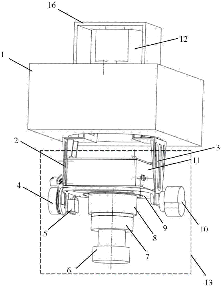
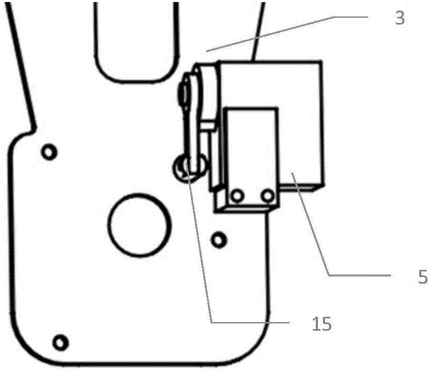
[0028] Specific implementation mode 1. Combination Figure 1 to Figure 4 Description of this embodiment, the aerial camera based on step-and-frame imaging includes a stable platform 1, a positioning and attitude determination system (POS system) 12, a boom 2 installed on the left, a boom 3 installed on the right, a motor 4, and an unlocked rudder Machine 5, camera 6, encoder 10, camera mounting plate 9, lens adapter 8, adapter plate 14.

[0029] Stabilizing platform 1 is erected in the aircraft cabin, and adapter plate 14 is erected on the top of stabilizing platform 2, and POS system 12 is installed, and the center of POS system 12 is aligned with the rotating shaft of stabilizing platform 2 inner frame, and POS system 12 is used for measuring the attitude angle of stabilizing platform 1 and Position coordinates, below the stable platform 2, the swinging mechanism 13 is hoisted by the left installation boom 2 and the right installation boom 3 respectively, and is suspended ou...

specific Embodiment approach 2

[0039] Specific embodiment two, combine Figure 5 to Figure 7 This embodiment is described. This embodiment is an aerial imaging method using the aerial imaging device based on step-and-framing imaging described in the first specific embodiment. The method is implemented by the following steps:

[0040] Step 1, before the sweeping mechanism 13 starts working, the camera 6 is at the initial position, and the photographing signal reading port reads the photographing signal from the mission management system of the aerial camera, and transmits it to the MCU, and the MCU receives the photographing signal Afterwards, send a photographing instruction to the camera 6, and the MCU reads the deflection angle of the camera 6 through the encoder reading port simultaneously, and stores the deflection angle of the camera 6 into the encoder information storage unit;

[0041] Step 2: After the MCU sends the command to take pictures to the camera 6 in step 1, wait for the camera to be exposed...


PUM


Abstract

The invention discloses an aerial photography based on stepping framing type image and an aerial photography method, and relates to the technical field of imaging. The invention solves the problems of complex structure, big volume, heavy device, fixed shooting angle and high price of the existing area array aerial photography. The aerial photography based on stepping framing type image comprises a stable platform, a POS system, a hanging arm, a motor, a steering engine, a camera, an encoder, a camera installing plate, a camera adapter, and a pin board; a swaying mechanism is hung at the lower part of the stable platform through the hanging arm structure, the pin board is erected at the upper part of the stable platform, and the POS system is mounted; the center of the POS system is aligned to a rotary shaft of the framework in the stable platform, both sides of the hanging arm are equipped with a motor and an encoder, the inside is fixed with the camera through the camera installing plate; the steering engine is fixed at inside of the camera installing plate. Through driving the motor, the front and back swaying movements of the swaying mechanism are realized, a big vision field swaying imaging is realized; a lateral image shift is compensated by means of the shooting mode of start-stop for many times; the camera and the high-precision POS system are miniaturized and integrated, the large-width high-resolution imaging is realized.

Description

technical field [0001] The invention relates to the field of imaging technology, in particular to an aerial camera based on stepping and framing imaging and an aerial imaging method. Background technique [0002] Aerial ground imaging is an important way to obtain ground target information. It is widely used in important fields such as terrain surveying and mapping, resource exploration, and military affairs. It uses various detection methods such as ultraviolet, visible light, infrared, and microwave to obtain and process ground object information. In order to realize the process of qualitative, positioning or quantitative description of ground objects. [0003] Large-scale wide and high-resolution are the development trend of aerial remote sensing infrared imaging. Large-scale wide imaging can cover a wider observation area and effectively improve work efficiency; high-resolution imaging can obtain target images with clearer and richer details and improve the accuracy of t...

Claims


Application Information

Patent Timeline
Patent Type & Authority Applications(China)
IPC IPC(8): G01C11/02
CPCG01C11/025
Inventor 王超屠志鹏李瑞峰赵春娟任迎张立媛齐宪阳
Owner CHANGGUANG SATELLITE TECH CO LTD
Learn More