Joint rehabilitation device

A joint and segment technology, applied in the field of joint rehabilitation devices, can solve the problems of high cost, difficult to control the degree of bending, heavy burden on patients, etc., and achieve the effects of avoiding injury, soft deformation, and low cost

Pending Publication Date: 2017-11-24
SUZHOU ROROBOT TECH CO LTD
View PDF9 Cites 8 Cited by
  • Summary
  • Abstract
  • Description
  • Claims
  • Application Information

AI Technical Summary

Problems solved by technology

At present, the rehabilitation of joints is mainly carried out in hospitals, and joint rehabilitation is performed by specialized medical equipment, which is costly and burdens patients heavily.
However, the current household portable joint rehabilitation devices mainly have two kinds of mechanical operations, which use pull wires to drive the joints to bend or open. However, this type of rehabilitation device has a relatively high risk, and the degree of bending is difficult to control, and once the device fails, Potential for bending transitions that directly cause irreparable damage to the joint

Method used


Image

  • Joint rehabilitation device
  • Joint rehabilitation device
  • Joint rehabilitation device

Examples


Embodiment 1

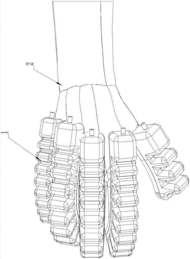
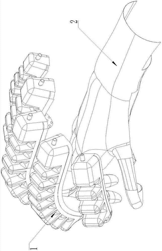
[0032] Such as Figure 1 to Figure 6 As shown, a joint rehabilitation device includes at least one flexible finger 1. The flexible finger 1 includes a finger bottom plate 11 and a finger finger surface 12, and the finger finger surface 12 is connected to one side of the finger bottom plate 11, The elastic modulus of the finger bottom plate 11 is greater than the elastic modulus of the finger finger surface 12, and the finger finger surface 12 and the finger bottom plate 11 together enclose the driving chamber 13, because the finger bottom plate 11 and the finger fabric have different elastic moduli Therefore, when a certain amount of gas or liquid is passed into the driving chamber 13, the amount of deformation of the finger bottom plate 11 and the finger surface 12 are different, thereby achieving bending deformation or opening deformation. The flexible finger 1 is made of elastic material. A vent 17 is provided on the finger finger surface 12 or the finger bottom plate 11, a...

Embodiment 2

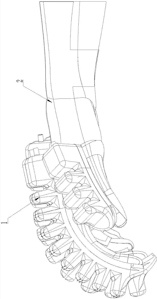
[0039] The structure of this embodiment is basically the same as that of embodiment 1, except that the joint rehabilitation device is not used for palm rehabilitation, but used for other joints, such as the elbow joint. At this time, the fixed structure includes a flexible The joint fixing sleeve 3 is made of material. The joint fixing sleeve 3 covers the entire joint from the first bone section A and extends to the second bone section B. The joint fixing sleeve 3 is provided with a clamp for fixing or loosening Connection structure. The detachable connection structure can be realized by using Velcro to realize quick connection, or it can also be realized by using a snap button.

[0040] In this embodiment, the size of the flexible finger 1 and the bottom of the wave trough 1222 of the finger segment 122 are embedded with a reinforcing sheet 16. The reinforcing sheet 16 is made of reinforcing fiber materials of other materials. The reinforcing sheet 16 can also enhance the comp...


PUM


Abstract

The invention discloses a joint rehabilitation device which comprises at least one flexible finger. Each flexible finger comprises a finger baseplate and a finger surface which is connected on one side plate face of the finger baseplate, elastic modulus of each finger baseplate is greater than that of the corresponding finger surface, each finger surface and the corresponding finger baseplate jointly surround to form a driving cavity, a ventilation port is arranged on each finger surface or the corresponding finger baseplate and communicated with an airway system through a pipeline, a fixing structure for fixing the corresponding flexible finger on a first bone section and a second bone section which form a joint is arranged on each finger baseplate, and each flexible finger covers the whole corresponding joint from the corresponding first bone section and extends to the corresponding second bone section. The joint rehabilitation device utilizes own deformation of the flexible fingers to drive the joints to act, in this way, rehabilitation action of bending or unfolding of the joints is comparatively gentle, and damage to the joints is avoided.

Description

Technical field [0001] The invention relates to a joint rehabilitation device, which can be applied in the medical industry. Background technique [0002] The joints between bones are called joints. The existence of joints allows the bones and bones to move with each other. Then, in stroke patients, it will cause upper limb disability. Upper limb disability, especially hand disability, affects the patient. Normal life. Therefore, for such patients, joint rehabilitation is particularly important. At present, the rehabilitation of joints is mainly performed in hospitals. Joint rehabilitation is performed by specialized medical equipment, which is costly and burdens patients. At present, portable joint rehabilitation devices for home use mainly have two mechanical operations, using cables to drive joints to bend or open. However, this type of rehabilitation device has a greater risk and the degree of bending is difficult to control, and once the equipment fails, It may cause bend...

Claims


Application Information

Patent Timeline
Patent Type & Authority Applications(China)
IPC IPC(8): A61H1/02A61F5/10
CPCA61F5/10A61H1/0218A61H1/0288B25J15/0023A61H2201/1238A61H2201/165A61H2205/067
Inventor 张帆
Owner SUZHOU ROROBOT TECH CO LTD
Why Eureka
Try Eureka