Layered-screening and drying equipment of coarse sand for architecture

A kind of drying equipment and technology for construction, which is applied in the field of coarse sand layer sieve drying equipment for construction, can solve the problems of unsteady control of the amount of sand added, high installation cost of screening equipment, and affecting the durability of concrete, etc., to achieve improvement Convenience, improvement of waste heat utilization efficiency, and effect of avoiding sand scattering

Inactive Publication Date: 2017-11-24
侯飞燕
View PDF0 Cites 5 Cited by
  • Summary
  • Abstract
  • Description
  • Claims
  • Application Information

AI Technical Summary

Problems solved by technology

The existing sand screening equipment cannot stably control the amount of sand added; the second is that the screen must be equipped with a vibrating motor to drive the screen to vibrate or drive the screen frame to vibrate through a reciprocating mechanism when screening, resulting in high installation costs for the screening equipment. The cost of screening increases, and it is inconvenient to collect the screened sand particles, which cannot be effectively used in construction
[0003] Sand is usually piled up in the open air. In a humid environment or in rainy and snowy weather, the water content in the sand will also increase. There will be a lot of water in the cracks or holes on the surface of the sand grains. During the construction process, due to the change of the water content of the sand It is necessary to adjust the amount of water added to the concrete mixture, and the reduction of the amount used will lead to the inconsistency of the concrete slurry, and structural defects will appear on the building after construction, which will affect the durability of the concrete.

Method used


Image

  • Layered-screening and drying equipment of coarse sand for architecture
  • Layered-screening and drying equipment of coarse sand for architecture
  • Layered-screening and drying equipment of coarse sand for architecture

Examples


Embodiment Construction

[0022] The following will clearly and completely describe the technical solutions in the embodiments of the present invention with reference to the accompanying drawings in the embodiments of the present invention. Obviously, the described embodiments are only some, not all, embodiments of the present invention. Based on the embodiments of the present invention, all other embodiments obtained by persons of ordinary skill in the art without making creative efforts belong to the protection scope of the present invention.

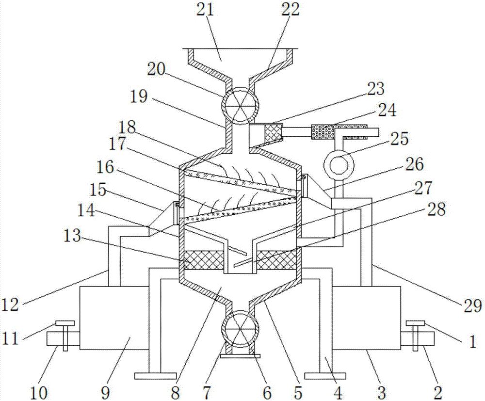
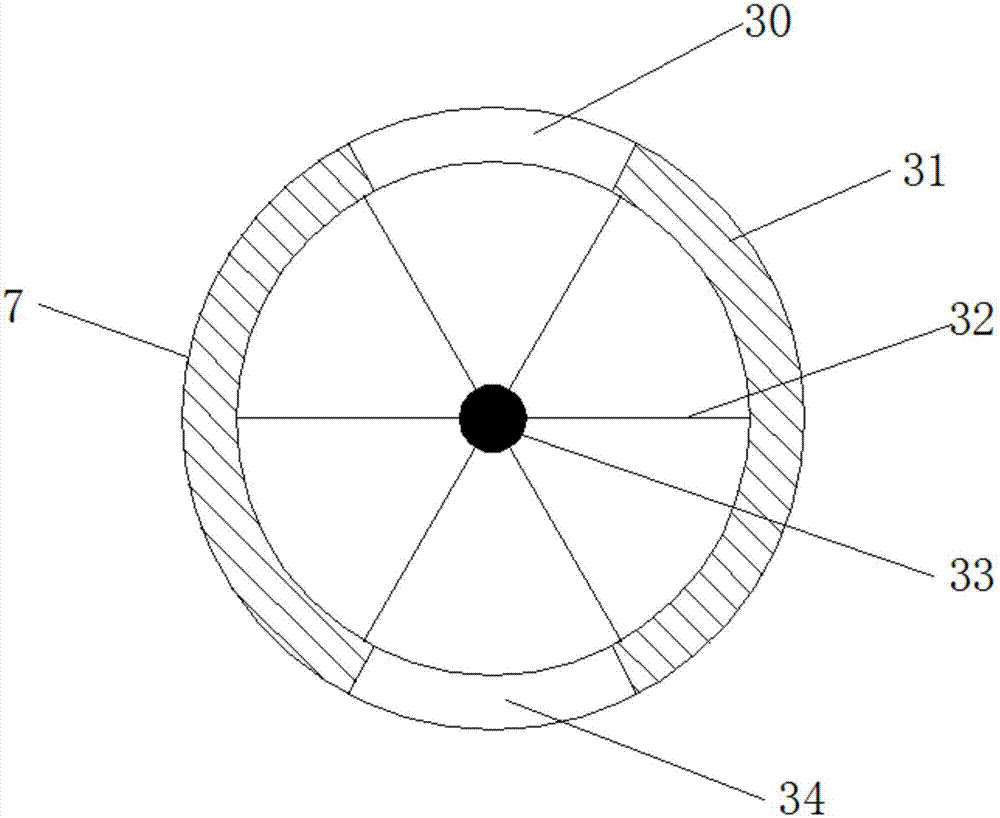
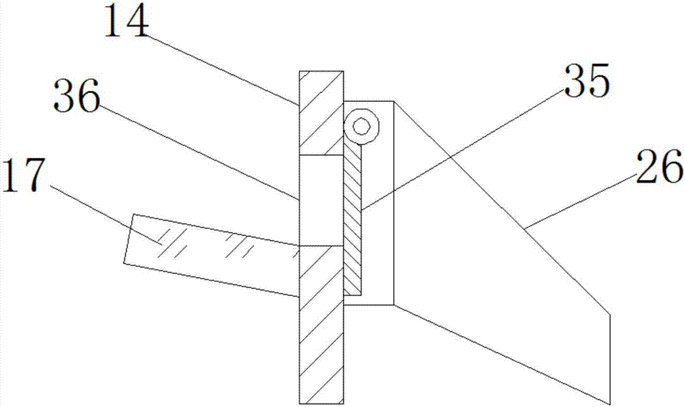
[0023] see Figure 1~4 , in the embodiment of the present invention, a coarse sand layer sieve drying equipment for construction, including a frame 4, a drying tank body 14, a secondary screen 16, a primary screen 17 and a heat exchange air duct 24, the The drying tank body 14 is installed on the frame 4, the middle part of the top of the drying tank body 14 is connected with the adding pipe 19, the top of the adding pipe 19 is connected with the quantitative ...


PUM


Abstract

The invention discloses a coarse sand layer sieve drying equipment for building, which comprises a frame, a drying tank body, a secondary screening net, a primary screening net and a heat exchange air duct. The drying tank body is installed on the frame On the top, the middle part of the top of the drying tank is connected to the adding pipe, and the top of the adding pipe is connected to the quantitative adding valve. The upper end of the quantitative adding valve is equipped with a sand adding bucket, and the inside of the sand adding bucket is set as an adding tank; the drying tank below the adding pipe The body is equipped with a first-level screen, and the drying tank below the first-level screen is equipped with a second-level screen; it is convenient to screen the sand added by the adding pipe step by step, and the blanking vibration reed is vibrated by the impact of the sand. Improve the efficiency and effect of sand screening, save the installation of vibrating motors, reduce production costs, can obtain sand with different particle sizes and is conducive to construction use, improve the waste heat utilization efficiency of exhaust air, reduce energy consumption, and reduce sand The cost of drying improves the efficiency and effect of sand drying.

Description

technical field [0001] The invention relates to the technical field of construction equipment, in particular to a coarse sand layer sieve drying equipment for construction. Background technique [0002] In building construction, sand is one of the essential basic raw materials. Due to its low price and easy access to materials, sand is widely used in the construction of concrete buildings. If the degree is uniform, it needs to be screened to remove the large grains of sand or sand mixed in it. The existing sand screening equipment cannot stably control the amount of sand added; the second is that the screen must be equipped with a vibrating motor to drive the screen to vibrate or drive the screen frame to vibrate through a reciprocating mechanism when screening, resulting in high installation costs for the screening equipment. The cost of screening increases, and it is inconvenient to collect the screened sand particles, which cannot be effectively used in building construc...

Claims


Application Information

Patent Timeline
Patent Type & Authority Applications(China)
IPC IPC(8): B07B9/00B07B1/28B07B1/42B07B1/46F26B21/00
CPCB07B9/00B07B1/28B07B1/42B07B1/46F26B21/001F26B21/004
Inventor 侯飞燕
Owner 侯飞燕
Why Eureka
Try Eureka