Device for cleaning inner surface of pipeline

A technology for cleaning devices and inner surfaces, which is applied in the direction of cleaning hollow objects, cleaning methods and utensils, chemical instruments and methods, etc., which can solve the problems of costing a lot of manpower and material resources, only dismantling or other methods, and many bends, etc. problem, to achieve the effect of saving manpower

Active Publication Date: 2017-11-24
GUANGZHOU SHIPYARD INTERNATIONAL LTD
View PDF5 Cites 13 Cited by
  • Summary
  • Abstract
  • Description
  • Claims
  • Application Information

AI Technical Summary

Problems solved by technology

During the production, installation and maintenance of the pipeline, some parts of the pipeline will be cleaned and treated. It cannot be completely manually entered into the pipeline for treatment, but can only be treated by dismantling the pipeline or other methods.
[0003] Some pipes have a long length and a large number of bends. When the inner surface of the pipe needs to be inspected, if the inner surface needs to be cleaned, the pipe section can only be removed; for pipes connected with detachable joints such as flanges, etc. The pipeline can be removed directly, but if the pipeline is connected by butt welding or sleeve welding, it needs to be cut before processing, especially when there are other objects blocking the welding connection position, the surrounding objects must be removed , it takes a lot of manpower and material resources, and takes a long time to work

Method used


Image

  • Device for cleaning inner surface of pipeline
  • Device for cleaning inner surface of pipeline
  • Device for cleaning inner surface of pipeline

Examples


Embodiment Construction

[0044] The technical solutions of the present invention will be further described below in conjunction with the accompanying drawings and through specific implementation methods.

[0045] In the description of the present invention, it should be understood that the orientation or positional relationship indicated by the terms "inner", "outer", etc. is based on the orientation or positional relationship shown in the drawings, and is only for the convenience of describing the present invention and simplifying the description. It is not intended to indicate or imply that the referred device or element must have a particular orientation, be constructed in a particular orientation, and operate in a particular orientation, and thus should not be construed as limiting the invention.

[0046] In addition, the terms "first", "second", and "third" are used for descriptive purposes only, and cannot be interpreted as indicating or implying relative importance or implicitly specifying the qua...


PUM


Abstract

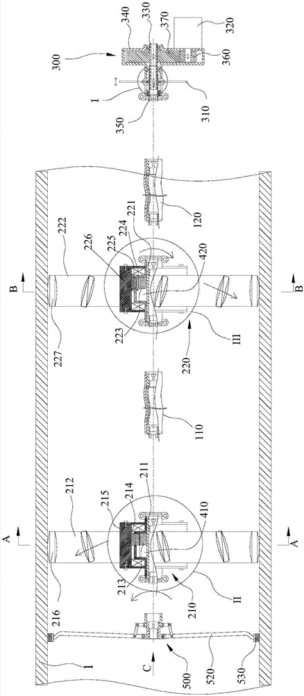
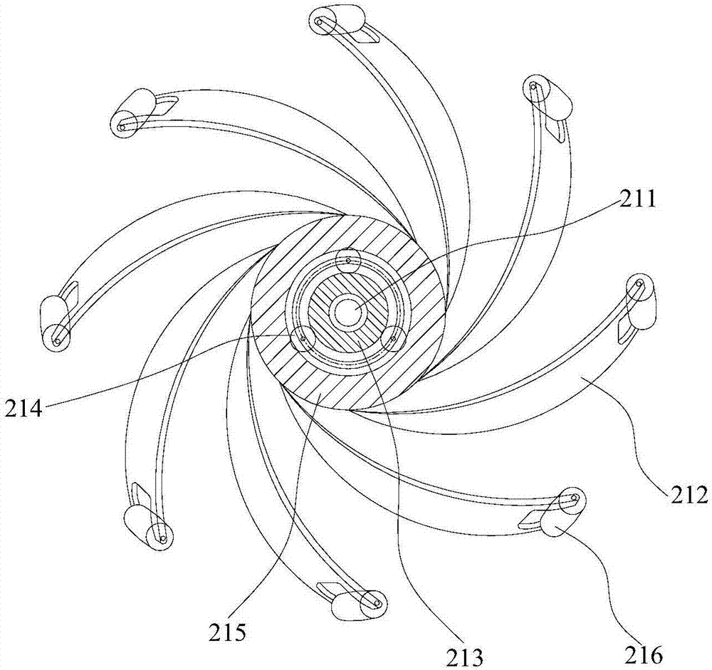
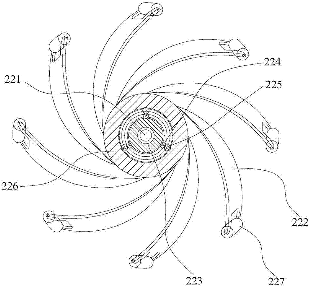
The invention discloses a device for cleaning the inner surface of a pipeline. The device comprises a transmission flexible shaft, a support, a driving device and a cleaning assembly. The transmission flexible shaft is provided with a first end and a second end which are opposite; the support is circular and is coaxially connected with the first end, and a plurality of idler wheels making contact with the inner wall of the pipeline are arranged on the periphery of the support at intervals; the driving device is connected with the second end, and the driving device can transfer the torsion to the support through the transmission flexible shaft so as to drive the support to move in the length direction of the pipeline; the cleaning assembly is located on the side, away from the driving device, of the support and coaxially connected with the support. By means of the device for cleaning the inner surface of the pipeline, it can be achieved that the cleaning assembly is conveyed to a preset position, the inner surface of the pipeline can be observed through the cleaning assembly, moreover, a to-be-transported object can be placed in front of the moving direction of the support, and the to-be-transported object is transported to the target position. Compared with the prior art, the pipeline does not need to be removed or cut, and a lot of manpower, material resources and time can be saved.

Description

technical field [0001] The invention relates to the technical field of pipeline system operation, in particular to a pipeline inner surface cleaning device. Background technique [0002] There are many types of pipeline systems in ships and industries, with various diameters, twists and turns, and different materials. During the production, installation and maintenance of the pipeline, certain parts of the pipeline will be cleaned and treated. It cannot be completely manually entered into the pipeline for treatment, but can only be treated by dismantling the pipeline or other methods. [0003] Some pipes have a long length and a large number of bends. When the inner surface of the pipe needs to be inspected, if the inner surface needs to be cleaned, the pipe section can only be removed; for pipes connected with detachable joints such as flanges, etc. The pipeline can be removed directly, but if the pipeline is connected by butt welding or sleeve welding, it needs to be cut ...

Claims


Application Information

Patent Timeline
IPC IPC(8): B08B9/027B08B9/045
CPCB08B9/027B08B9/045
Inventor 何家骥文华平李国云李新张瑞华
Owner GUANGZHOU SHIPYARD INTERNATIONAL LTD
Why Eureka
Try Eureka