Pneumatic pipe bender

A pipe bending machine and pipe bending technology, which is applied in the field of machinery manufacturing equipment, can solve problems such as low work efficiency, poor compatibility, and poor work stability, and achieve the effects of reducing unqualified workpieces, reducing labor costs, and avoiding offset

Inactive Publication Date: 2017-11-24
ANHUI SHENGMEI METAL TECH CO LTD
View PDF5 Cites 6 Cited by
  • Summary
  • Abstract
  • Description
  • Claims
  • Application Information

AI Technical Summary

Problems solved by technology

[0003] In the existing technology, the traditional pipe bending machine has problems such as low working efficiency, poor working stability, and easy damage to parts during use. The traditional pipe bending machine cannot ensure that the workpiece does not deviate when bending the workpiece. and the bending compatibility of workpieces of different sizes is poor. The top bending mechanism cannot maintain stability when bending the workpiece, and the workpiece will be shifted during the top bending, resulting in unqualified workpieces and waste of workpieces. , increasing labor costs

Method used


Image

  • Pneumatic pipe bender
  • Pneumatic pipe bender
  • Pneumatic pipe bender

Examples


Embodiment Construction

[0033] Below in conjunction with accompanying drawing and embodiment of description, specific embodiment of the present invention is described in further detail:

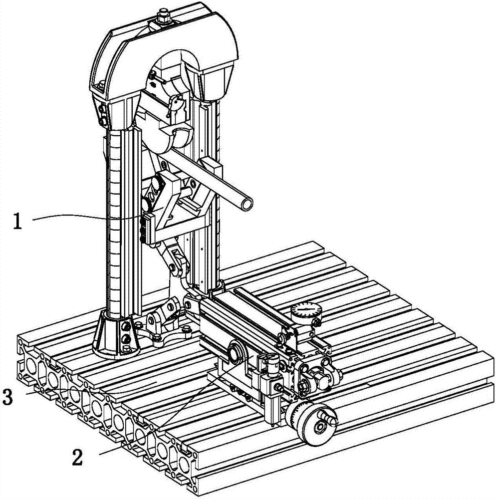
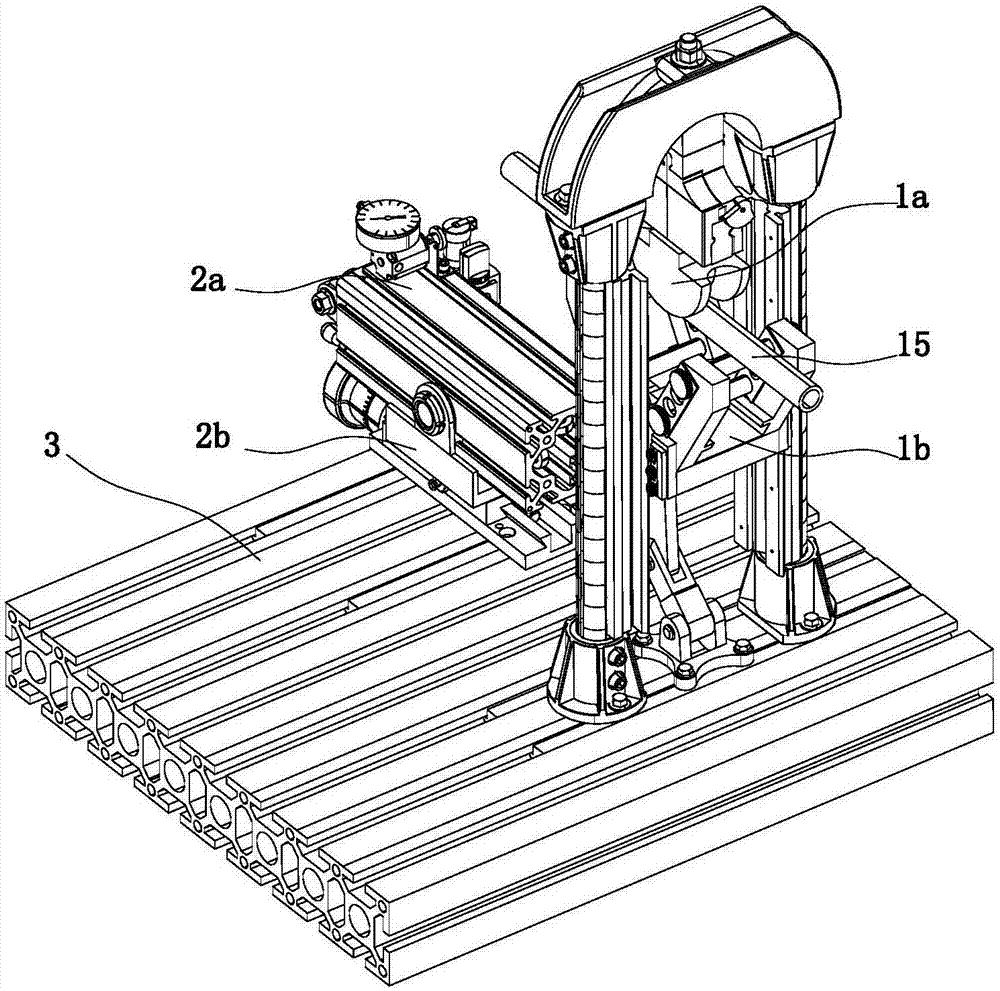
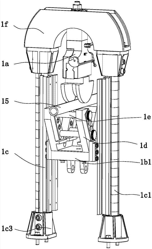
[0034] refer to Figure 1 to Figure 17 A pneumatic pipe bending machine shown includes a pipe bending device 1, a pipe bending driving device 2 and a base 3 for driving the pipe bending device 1 to achieve pipe bending, and the pipe bending device 1 includes a shaping mechanism 1a and a top bending mechanism 1b And two slides 1c for the top bending mechanism 1b to slide, all the slides 1c are arranged vertically and at intervals, the shaping mechanism 1a is arranged on the top of the sliding path 1c, and the top bending mechanism 1b is arranged directly below the shaping mechanism 1a The sizing mechanism 1a includes a locking mechanism 1a1, a sizing mold 1a2 and a limit mechanism 1a3 for preventing the sizing mold 1a2 from shifting, the bottom end of the locking mechanism 1a1 is fixedly connected with the sizing mol...


PUM


Abstract

The invention relates to the field of mechanical manufacturing equipment, in particular to a pneumatic pipe bending machine, which includes a pipe bending device, a pipe bending drive device and a base for driving the pipe bending device to achieve pipe bending, and the pipe bending device includes a shaping mechanism and a top bending mechanism And two slideways for the top bending mechanism to slide, the shaping mechanism is arranged on the top of the slideway, the top bending mechanism is provided with a first roller that cooperates with the slideway on the side close to the slideway, and the top bending mechanism includes a support plate 1. The clamping arm set on the top of the support plate and the clamping rod set that runs through the clamping arm set and is arranged horizontally, the bending pipe driving device includes a guide slide channel, an adjustment mechanism and a drive mechanism arranged at the bottom of the guide slide channel, The pipe bending driving device of the present invention drives the top bending mechanism to rise, and the first rollers of the top bending mechanism arranged on both sides of the slideway slide and cooperate with the slideway to ensure that the top bending mechanism rises steadily along the slideway, and the shaping mechanism and the top bender Cooperate with the top bending of the workpiece, it can maintain stability and avoid the workpiece from shifting during the top bending.

Description

technical field [0001] The invention relates to the field of mechanical manufacturing equipment, in particular to a pneumatic pipe bender. Background technique [0002] Pipe bending machines can be roughly divided into CNC pipe bending machines, hydraulic pipe bending machines and so on. The pipe bender mainly uses hydraulic pressure to perform winding bending of the pipe body with one bending radius or two bending radii in a cold state, and is widely used in bending various workpieces and wires in industries such as automobiles and air conditioners. [0003] In the existing technology, the traditional pipe bending machine has problems such as low working efficiency, poor working stability, and easy damage to parts during use. The traditional pipe bending machine cannot ensure that the workpiece does not deviate when bending the workpiece. and the bending compatibility of workpieces of different sizes is poor. The top bending mechanism cannot maintain stability when bending...

Claims


Application Information

Patent Timeline
Patent Type & Authority Applications(China)
IPC IPC(8): B21D7/06
CPCB21D7/06
Inventor 凌永娥
Owner ANHUI SHENGMEI METAL TECH CO LTD
Why Eureka
Try Eureka