Stamping mould mechanical arm

A technology of stamping dies and manipulators, applied in the field of stamping dies and manipulators, can solve problems such as imperfect technology, easy to drop, and reduced use value of equipment

Inactive Publication Date: 2017-11-24
广州市鹭江远科技有限公司
View PDF1 Cites 3 Cited by
  • Summary
  • Abstract
  • Description
  • Claims
  • Application Information

AI Technical Summary

Problems solved by technology

[0004] In view of the deficiencies in the existing technology, the purpose of the present invention is to provide a stamping die manipulator t

Method used


Image

  • Stamping mould mechanical arm
  • Stamping mould mechanical arm

Examples


Embodiment Construction

[0018] In order to make the technical means, creative features, goals and effects achieved by the present invention easy to understand, the present invention will be further described below in conjunction with specific embodiments.

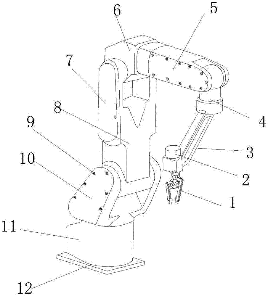
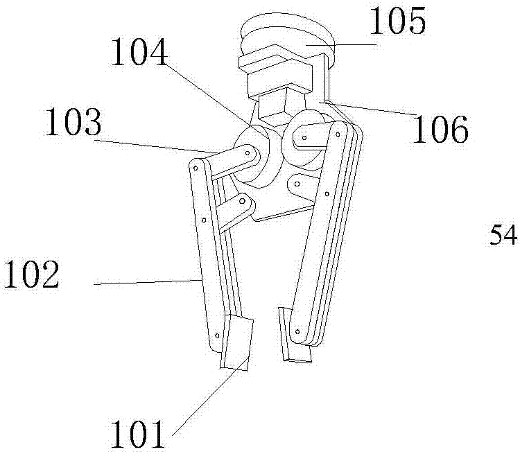
[0019] see figure 1 , figure 2 , the present invention provides a stamping die manipulator technical solution: its structure includes a flexible grasping device 1, a connecting head 2, a pole 3, a wrist 4, a small arm 5, an elbow 6, a fixed plate 7, a large arm 8, a fixed Bolt 9, shoulder 10, base 11, bottom plate 12, the top of the flexible grasping device 1 is located at the bottom of the connector 2, the top of the connector 2 is welded to the front end of the pole 3, the rear end of the pole 3 is connected to the wrist 4 is internally rotated and connected, the top of the wrist 4 is flexibly connected to the front end of the forearm 5, the top of the forearm 5 is fixedly connected to the bottom of the elbow 6, and the side of the top of the...


PUM


Abstract

The invention discloses a stamping die manipulator, the structure of which comprises a flexible grasping device, a connecting head, a support rod, a wrist, a forearm, an elbow, a fixed plate, a large arm, a fixed bolt, a shoulder, a base, and a bottom plate; The grabbing device consists of a non-slip grabbing plate, fingers, a transmission rod, a turntable, a rotating shaft, and a fixed palm. The non-slip grabbing plate is installed on the inner side of the finger, and the finger is connected to the rotating shaft through the driving rod. The bottom of the rotating shaft is vertically connected to the front side of the fixed palm. The top of the fixed palm is movably connected to the bottom of the rotating shaft, and the top of the rotating shaft is fixed to the bottom of the connecting head. The manipulator of the stamping die of the present invention adds a flexible grasping device, which is flexible enough when grasping, and can also be rotated to pick up parts, which is not easy to drop and tight. Solidity is better.

Description

technical field [0001] The invention relates to a stamping die manipulator, which belongs to the field of stamping die manipulators. Background technique [0002] In today's life, with the rapid development of science and technology, the biggest difference between robotic arms and human arms lies in flexibility and endurance. [0003] The prior art published application number is: 201620272710.4 The invention relates to the field of mechanical automation, specifically to a four-axis swing arm manipulator, the first axis is connected to the second axis through a ball screw, and the second axis is rotated The rod is connected to the third shaft part, the fourth shaft part is installed on the third shaft part, the first motor of the first shaft part is fixed on the base, the first motor drives the ball screw to rotate through the pulley, and the second The rotating base of the shaft is installed on the ball screw, the rotating rod is fixed on the rotating base, the second moto...

Claims


Application Information

Patent Timeline
IPC IPC(8): B25J9/00
CPCB25J9/00
Inventor 齐宽宽
Owner 广州市鹭江远科技有限公司
Why Eureka
Try Eureka