Linear supersonic motor-based two-finger parallel connection micro operation hand and operation method

A linear ultrasonic motor and ultrasonic motor technology, applied in the field of biomedical engineering, can solve problems such as limiting the ability of micro-manipulators

Inactive Publication Date: 2014-07-30
NANJING UNIV OF AERONAUTICS & ASTRONAUTICS
View PDF6 Cites 4 Cited by
  • Summary
  • Abstract
  • Description
  • Claims
  • Application Information

AI Technical Summary

Problems solved by technology

The method of directly using the piezoelectric ceramic static deformation and displacement

Method used


Image

  • Linear supersonic motor-based two-finger parallel connection micro operation hand and operation method
  • Linear supersonic motor-based two-finger parallel connection micro operation hand and operation method
  • Linear supersonic motor-based two-finger parallel connection micro operation hand and operation method

Examples


Embodiment Construction

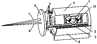
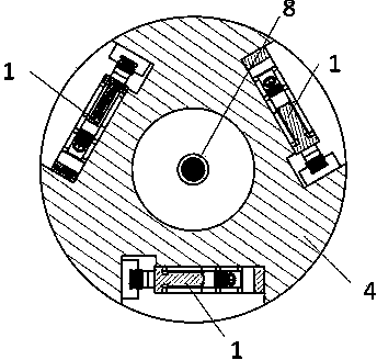
[0020] A three-degree-of-freedom two-finger parallel micromanipulator based on a linear ultrasonic motor, the manipulator includes an arm and a hand, such as image 3 shown.

[0021] The arm and hand of the operating hand include three linear ultrasonic motors 1, guide rail 2, slider 3, arm 4, flexible joint 5, disc 6, short finger 7, long finger 8, base 9, motor stator 10, Such as image 3 shown. Three linear ultrasonic motors 1 are evenly distributed around the central axis of the arm 4, with a difference of 120° between any two, such as figure 2 shown. Each linear guide rail 2 is respectively connected with a flexible joint 5, and three flexible joints 5 are connected with the disc 6 and controlled to move to form a three-degree-of-freedom parallel motion. The long fingers 8 are fixed on the arm 4 and pass through the central hole of the disc 6 , and the short fingers 7 are fixed on the disc 6 at an angle of 20°-25°, forming chopsticks with the long fingers 8 . The lo...


PUM


Abstract

The invention discloses a linear supersonic motor-based three-freedom degree two-finger parallel connection micro operation hand method and belongs to the field of biomedical engineering. An operation hand comprises an arm, linear supersonic motors, flexible joints, a disc, a long finger, a short finger and a base, wherein the arm is fixed on the base, the three linear supersonic motors are all formed by stators and sliders which are fixed on the arm as well as linear guide rails positioned between driving feet of the stators and the sliders; the three linear supersonic motors are uniformly distributed around the middle axis of the arm and are differenced by 120 degrees two by two. The disc is arranged at the tail ends of the guide rails of the linear supersonic motors by the flexible joints; the long finger is fixed on the arm, and the fingertip of the long finger penetrates through a central hole in the disc; the finger root of the short finger is fixed on the disc. The operation hand is compact in structure and simple in control method, and has larger operation range and higher location precision.

Description

technical field [0001] The invention discloses a three-degree-of-freedom two-finger parallel micromanipulator based on a linear ultrasonic motor and an operation method, which belong to the field of biomedical engineering and industrial fields such as microencapsulation that require precise positioning and grasping. Background technique [0002] In the field of biomedical engineering, genetic engineering, animal and plant cloning, chromosome analysis and artificial insemination all take cells as the research objects. In order to perform operations such as grasping, flipping, puncturing, injecting, cutting, and removing nuclei on cells of a few microns, robotic hands (also known as micromanipulators) that can perform the above operations on cells are needed. The micromanipulator is an electromechanical system on a macroscopic structure, but it takes micro and nano structures as its operating objects, and belongs to the research scope of micro and nano manufacturing science an...

Claims


Application Information

Patent Timeline
IPC IPC(8): B25J9/00B25J7/00
Inventor 姚志远耿冉冉王赟
Owner NANJING UNIV OF AERONAUTICS & ASTRONAUTICS
Why Eureka
Try Eureka