

Brick moving clamp and intelligent brick stacking robot based on visual identification
A visual recognition and robot technology, applied in the field of automatic palletizing, can solve the problems of less research and application of shape and positioning, and achieve the effects of saving manpower and material resources, high adjustment accuracy, and avoiding boring operations
- Summary
- Abstract
- Description
- Claims
- Application Information
AI Technical Summary
Problems solved by technology
Method used
Image

Examples
Embodiment 1
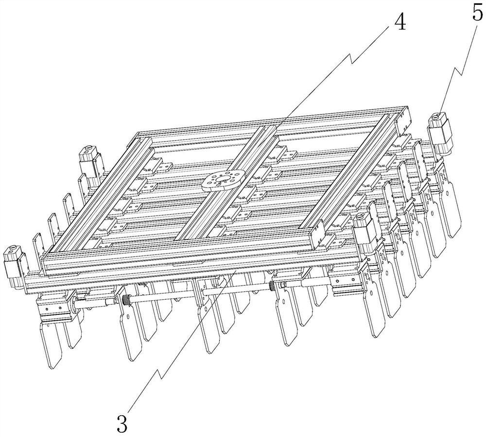
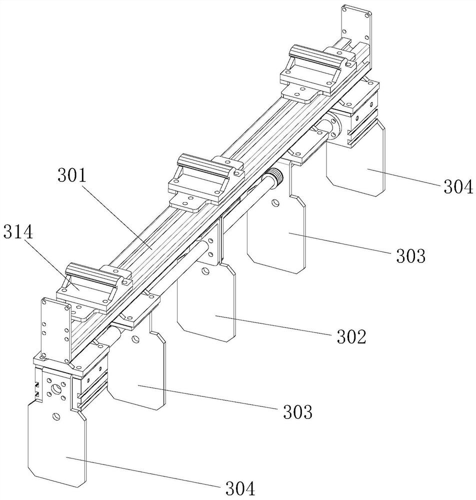
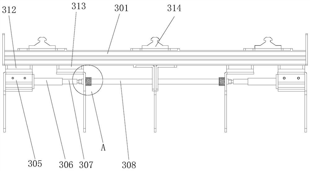
[0037] Such as Figure 1~4 As shown, a brick moving jig includes a clamping mechanism 3, the clamping mechanism includes a guide rail 301, a fixed clip 302 and a clamping assembly, and the clamping assembly includes a telescopic member, a first clip 304, a second clip 303, Push rod 306, the fixed clip is fixedly connected with the guide rail, the first clip and the second clip are respectively slidably connected to the guide rail, the first clip, the second clip and the fixed clip are arranged in parallel, and the second clip is located on the first clip Between the clip and the fixed clip, the telescopic piece is respectively connected to the first clip and the fixed clip, so that the expansion and contraction of the telescopic piece drives the first clip away from or close to the fixed clip, and the push rod is located between the first clip and the second clip Between, the ejector rod is fixedly connected with the first clip, and one end of the ejector rod faces the second ...
Embodiment 2
[0056] Such as Figure 11 As shown, when an intelligent code brick robot based on visual recognition is applied, the intelligent code brick robot based on visual recognition is fixedly installed between two brick cutters placed side by side through the base, and the outside of one brick cutter is also A robot spare station 14 is provided, and a backing board collection platform 15 is provided at the exit of the brick cutting machine. The backing board collection table is covered with cut bricks, and 4 trays placed in a rectangular lattice are arranged in front. Area B is the active area of the mechanical arm of the five-axis manipulator, and the backing plate collection table and 4 pallets are located in area B.
[0057] After the visual recognition device detects the brick embryo information on the backing plate collection platform in the active area of the mechanical arm, the robot responds, quickly grabs the brick blank through the grabbing fixture, and places it on the...
Embodiment 3
[0060] Such as Figure 12 As shown, when an intelligent code brick robot based on visual recognition is applied, the intelligent code brick robot based on visual recognition is fixedly installed between two brick cutters placed side by side through the base, and the exit of the brick cutter is provided with Backing plate collection table, the cut bricks are laid on the backing plate collection table, there are 4 trays placed in a circular lattice in front, and a third brick cutting machine is placed in front of the code blank placement point. Area C is the active area of the mechanical arm on the five-axis manipulator, and the backing plate collection platform and 4 pallets are located in area C.
[0061] The parts not mentioned in this embodiment are the same as those in Embodiment 2.
PUM
 Abstract
Description
Claims
Application Information