Spare wheel up-down regulator assembly with steel wire rope

A technology of wire rope and lifter, which is applied in the field of car spare tire lifting device, can solve the problems of complex transmission structure and high failure rate, and achieve the effects of improved manufacturing process, high torsional strength and stable operation

Pending Publication Date: 2017-11-24
张俊华
View PDF11 Cites 1 Cited by
  • Summary
  • Abstract
  • Description
  • Claims
  • Application Information

AI Technical Summary

Problems solved by technology

But the rotating shaft of this lifter is a straight rod, and the rotating shaft passes through the rotating plate, the opposite sex spring, the spring frame welding assembly (including the spring frame and the eccentric sleeve), and the working mode is that the hexagonal hole on the rotating shaft drives the rotating plate to rotate , the rotating plate drives the spring frame welding assembly to rotate, and the eccentric sleeve on the spring frame welding assembly drives the gear to rotate. The transmission structure is complex and the failure rate is high during use.

Method used


Image

  • Spare wheel up-down regulator assembly with steel wire rope
  • Spare wheel up-down regulator assembly with steel wire rope
  • Spare wheel up-down regulator assembly with steel wire rope

Examples


Embodiment 1

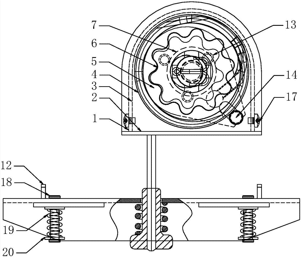
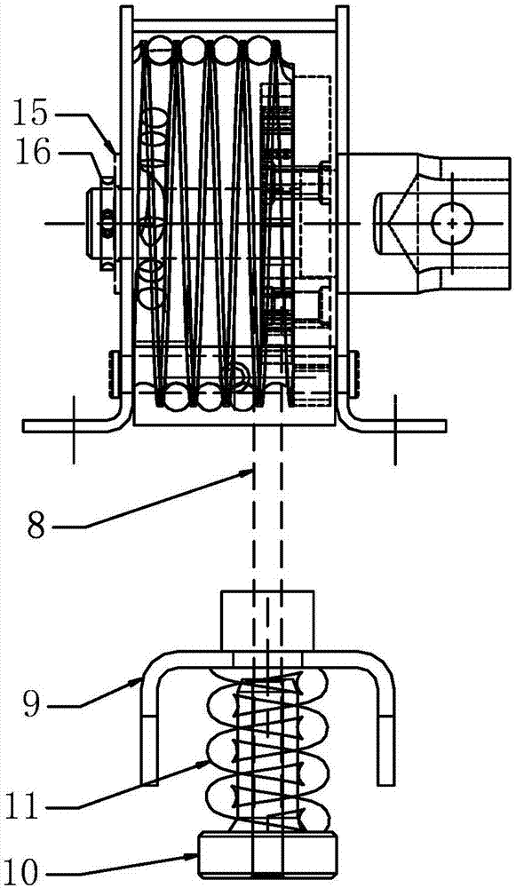
[0023] refer to Figure 1-5 , a wire rope spare tire lifter assembly, comprising a housing 1, the outer side of the housing 1 is fixedly connected with a protective cover 2 through screws 17, the side of the protective cover 2 is fixedly connected with a side blocking piece 3, and the housing 1 is movable and socketed There is an eccentric shaft 7, the guiding iron 5 is sleeved on the eccentric shaft 7, the guiding iron 5 and the ratchet 6 are riveted through the first rivet 13, the ratchet 6 meshes with the winding gear 4, and the winding gear 4 is wound with a wire rope 8, The wire rope 8 is fixedly sleeved with a hanger 9, and the end of the wire rope 8 is fixedly connected with a lock head 10. The lock head 10 and the hanger 9 are equipped with a first spring body 11, and the first spring body 11 is sleeved on the outside of the wire rope 8. The frame 9 is symmetrically equipped with two clips 12, the clips 12 are fixed on the hanger 10 by the third rivet 18, the outside o...

Embodiment 2

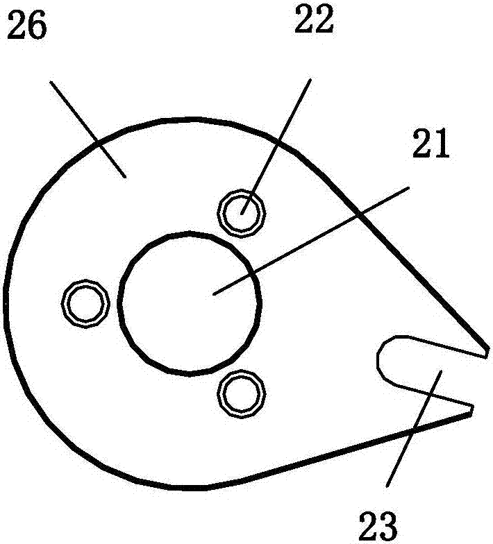
[0027] refer to Figure 6 , this embodiment is an improvement on the structure of the hanger on the basis of Embodiment 1. The shape of the clamping plate 12 is hexagonal, and the clamping plate 12 and the hanger 9 are movably connected by a rotating shaft 25 , and the rotating shaft 25 and the clamping plate 12 are arranged eccentrically. In this embodiment, the distance between the two clamping plates 12 can be adjusted by rotating the clamping plates 12 and using the structure that the clamping plates 12 rotate eccentrically around the rotating shaft 25 , so as to adapt to wheel hubs of different sizes.


PUM


Abstract

The invention discloses a spare wheel up-down regulator assembly with a steel wire rope. The spare wheel up-down regulator assembly comprises a shell, a protective cover is fixedly connected to the outer side of the shell through screws, a side plug piece is fixedly connected to the lateral side of the protective cover, an eccentric shaft movably internally sleeves the shell, alignment guide iron sleeves the eccentric shaft and pivoted to a ratchet wheel through first rivets, the ratchet wheel is meshed with a winding gear, the steel wire rope is wound on the winding gear, a hanging frame fixedly sleeves the steel wire rope, and a lock head is fixedly connected to the tail end of the steel wire rope. A first spring body is mounted on the locking head and the hanging frame and externally sleeves the steel wire rope, two clamping plates are symmetrically mounted on the hanging frame and fixed to the hanging frame through third rivets, second spring bodies externally sleeve the third rivets, and two ends of each second spring body are connected with round washers. The spare wheel up-down regulator assembly with the steel wire rope has advantages that defects in the prior art can be overcome, complexity of a transmission structure is reduced, and convenience in use is achieved.

Description

technical field [0001] The invention relates to an automobile spare tire lifting device, in particular to a wire rope spare tire lifter assembly. Background technique [0002] When the car is running, it needs to be equipped with a spare tire so that the damaged tire during driving can be replaced at any time. In order to increase the space in the car, some models adopt an external spare tire. When taking the spare tire, the spare tire needs to be disassembled and installed by the spare tire lifter. Chinese invention patent CN 104973147A discloses a spare tire lifter assembly, which drives the supporting plate to move up and down by the steel wire rope through the rotating gear to realize the lifting operation of the spare tire. But the rotating shaft of this lifter is a straight rod, and the rotating shaft passes through the rotating plate, the opposite sex spring, the spring frame welding assembly (including the spring frame and the eccentric sleeve), and the working mode...

Claims


Application Information

Patent Timeline
Patent Type & Authority Applications(China)
IPC IPC(8): B62D43/04
CPCB62D43/045
Inventor 张俊华马五胜王志远张嘉益
Owner 张俊华
Why Eureka
Try Eureka