Rotor for synchronous reluctance motor

A synchronous reluctance motor and rotor technology, applied in the direction of magnetic circuit rotating parts, magnetic circuit, electrical components, etc., can solve the problems of motor magnetic flux leakage, high temperature demagnetization of permanent magnet motor, low material utilization rate, etc., and improve the air gap. Magnetic density and power density, the effect of increasing the magnetic flux per pole, and increasing the speed range

Pending Publication Date: 2019-04-16
苏州英磁新能源科技有限公司
View PDF0 Cites 3 Cited by
  • Summary
  • Abstract
  • Description
  • Claims
  • Application Information

AI Technical Summary

Problems solved by technology

However, as the price of permanent magnet materials rises, the production cost increases, and the demand for high-performance drive motors, due to the built-in permanent magnet structure motor flux leakage, reluctance characteristics are not outstanding, material utiliza

Method used


Image

  • Rotor for synchronous reluctance motor
  • Rotor for synchronous reluctance motor
  • Rotor for synchronous reluctance motor

Examples


Example Embodiment

[0031] The technical solutions of the present invention will be clearly and completely described below in conjunction with the accompanying drawings. Obviously, the described embodiments are part of the embodiments of the present invention, rather than all of them. Based on the embodiments of the present invention, all other embodiments obtained by those of ordinary skill in the art without creative work shall fall within the protection scope of the present invention.

[0032] First define some abbreviations or professional terms involved in the present invention:

[0033] Reluctance motor: It is a continuous-running electric transmission device. Its structure and working principle are very different from traditional AC and DC motors. It does not rely on the interaction of the magnetic fields generated by the stator and rotor winding currents to generate torque, but relies on the "principle of minimum reluctance" to generate torque.

[0034] Quadrature axis: The quadrature axis is a...


PUM


Abstract

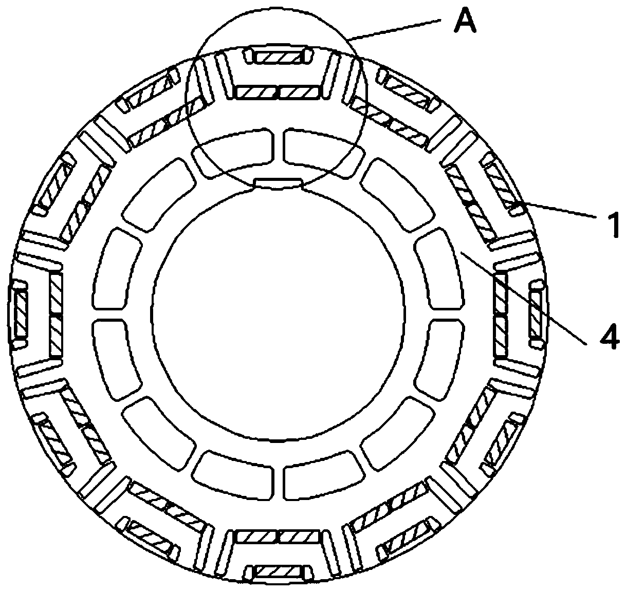
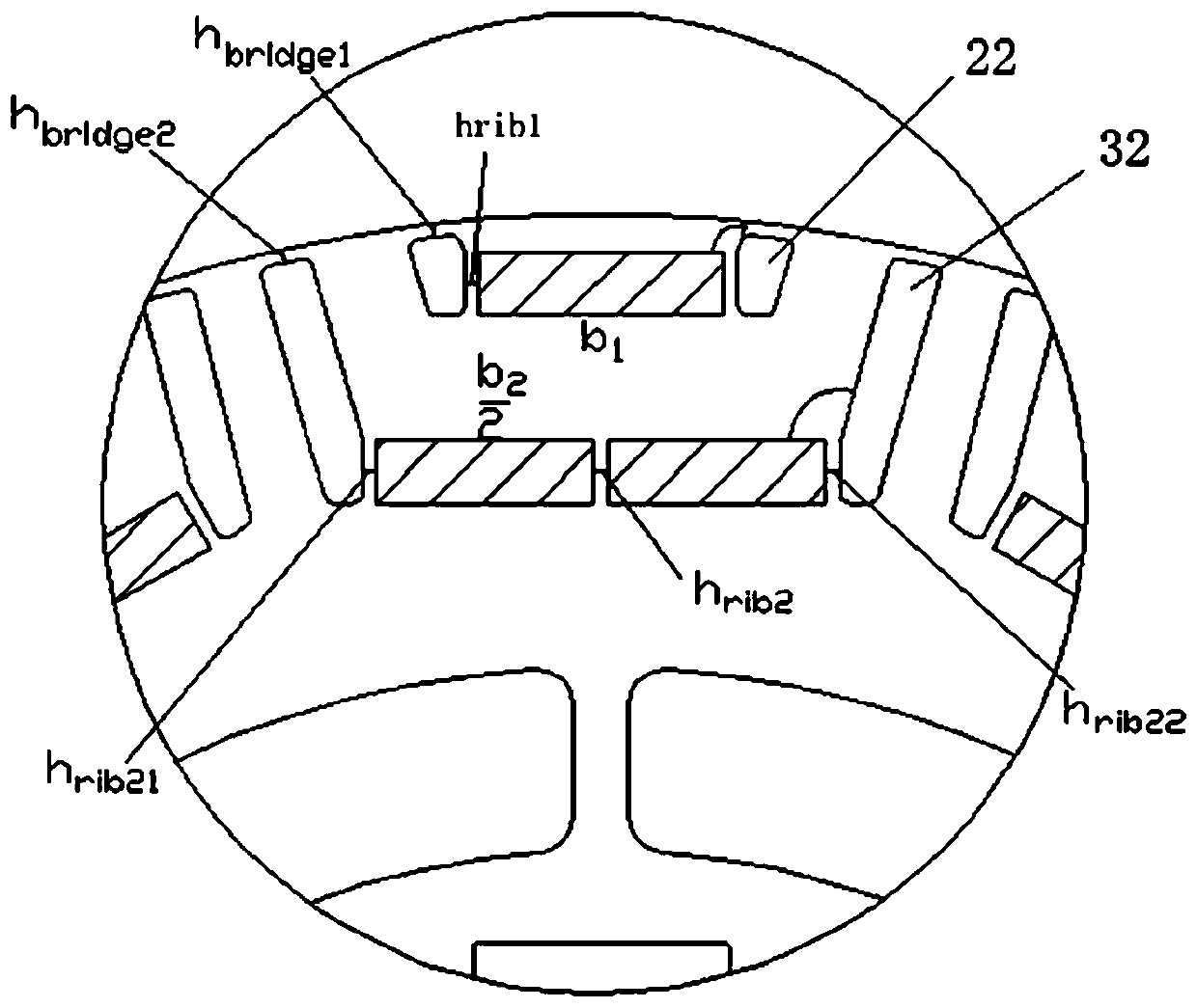
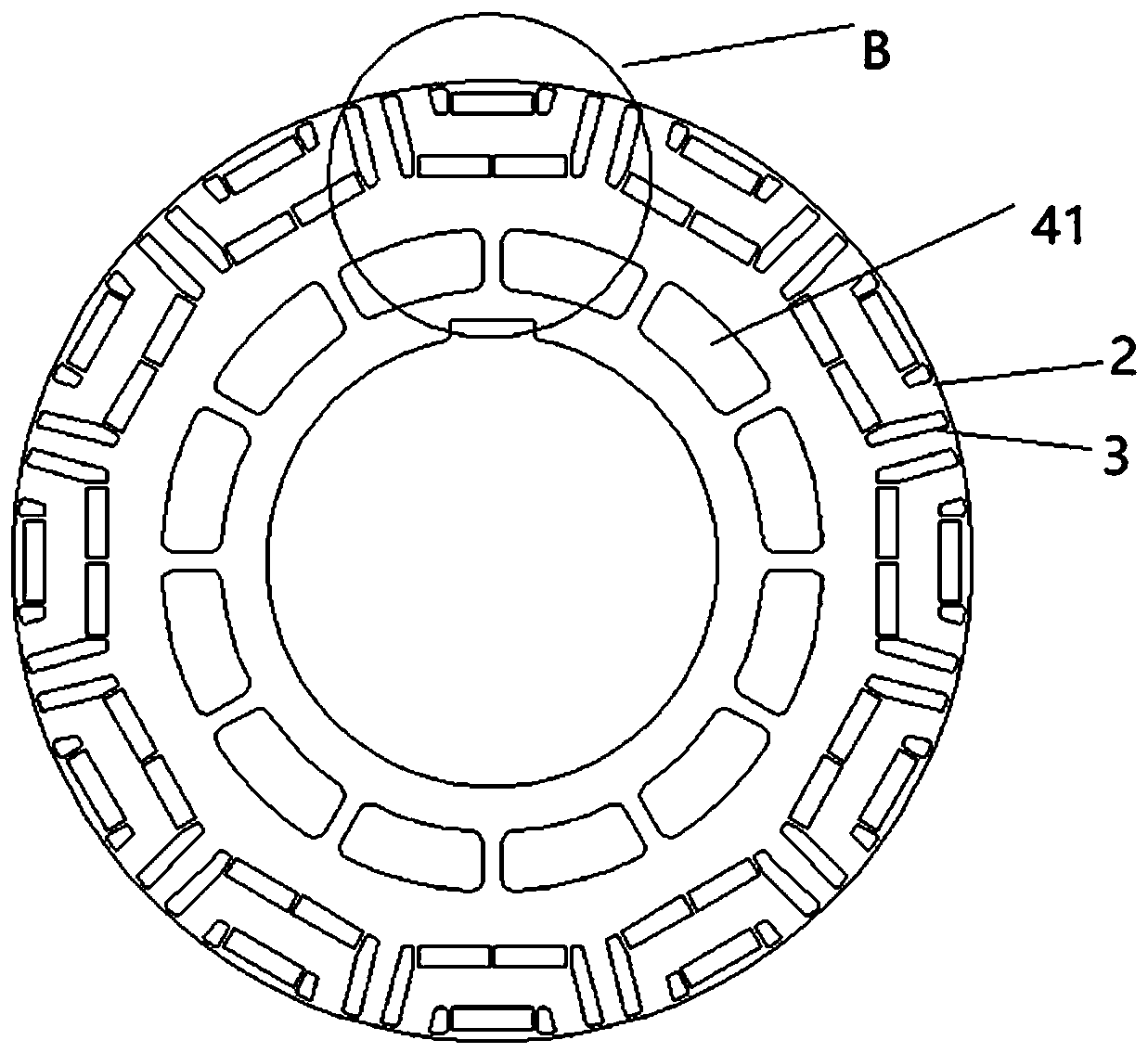
The invention relates to a rotor structure for a synchronous reluctance motor. A plurality of groups of air layer structures are distributed in the circumferential direction of a rotor. A circle of lightening holes are formed in the middle of the rotor, and each air layer structure comprises a first layer of air groove group and a second layer of air groove group. The first air groove set comprises a first straight-axis air groove formed in the middle, and the two sides of the first straight-axis air groove are each provided with a first quadrature-axis air groove. The second air groove set comprises two second straight-axis air grooves formed in the middle, and a second quadrature-axis air groove is formed in the outer side of each second straight-axis air groove. Through structural optimization processing, arrangement of the air grooves, arrangement of the reinforcing ribs and placement of the magnetic steel, the peak torque, efficiency and power factors of the motor are effectivelyimproved, the counter electromotive force of a high-speed weak magnetic area is reduced, and the speed regulation range of the motor is remarkably improved.

Description

technical field [0001] The invention relates to the technical field of synchronous reluctance motors, in particular to a rotor structure for synchronous reluctance motors, in particular to a rotor structure with double air layers. Background technique [0002] With the development of power electronics technology and control theory, permanent magnet synchronous reluctance machine (Synchronous Reluctance Machine) referred to as SynRM is widely used in industrial and agricultural production, transportation, national defense, Commercial and household appliances, medical electrical equipment and other fields. [0003] At present, the rotor structure of permanent magnet synchronous reluctance motor is mainly built-in type. Because of its certain reluctance performance, it has become the main rotor structure used in new energy vehicle drive motors. However, as the price of permanent magnet materials rises, the production cost increases, and the demand for high-performance drive mo...

Claims


Application Information

Patent Timeline
IPC IPC(8): H02K1/27
CPCH02K1/274H02K2213/03
Inventor 裴瑞琳张翔建王丽慧
Owner 苏州英磁新能源科技有限公司
Why Eureka
Try Eureka