A Canned Pump with Forced Cooling and Lubricating Function

A technology of forced cooling and shielded pumps, which is applied to parts, pumps, and pump components of elastic fluid pumping devices, and can solve the problems of easy wear of friction pairs, high heat generation, and easy burning of motor windings, etc. The life of the pump, the improvement of reliability, and the effect of enhancing the lubrication and cooling effect

Active Publication Date: 2020-06-26
JIANGSU UNIV
View PDF7 Cites 0 Cited by
  • Summary
  • Abstract
  • Description
  • Claims
  • Application Information

AI Technical Summary

Problems solved by technology

[0003] In order to overcome the problems of large internal heat generation of high-power and high-speed shielded pumps, easy burning of motor windings and easy wear of friction pairs, the invention proposes a shielded pump with forced cooling and lubrication function

Method used


Image

  • A Canned Pump with Forced Cooling and Lubricating Function

Examples


Embodiment Construction

[0017] The present invention will be further described below in conjunction with the accompanying drawings and specific embodiments, but the protection scope of the present invention is not limited thereto.

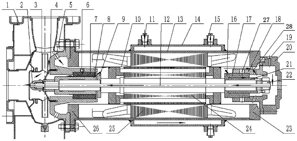
[0018] Such as figure 1 As shown, the canned pump with forced cooling and lubricating function of the present invention includes a pump body 1, an impeller nut 2, an impeller 4, a front bearing seat 4, a front sliding bearing 7, a shaft sleeve 8, a front thrust plate 9, a shielding Sleeve 10, shaft 12, motor housing 13, jacket 14, rear thrust plate 16, rear sliding bearing 17, rear bearing seat 18, motor rear cover plate 20, shaft sleeve 2 21, nut 22, motor rear end cover 23, Motor rotor winding 24, motor stator winding 25, motor front end cover 26, the impeller 3 is located inside the pump body 1 and fixed on one end of the shaft 12 through the impeller nut 2, the front bearing seat is located on the far pump side of the impeller , the shaft sleeve 1 8, the front slidin...


PUM


Abstract

The invention provides a shield pump with forced cooling and lubricating functions. A front bearing pedestal and a rear sliding bearing pedestal are each provided with two through holes. A gap is reserved between a front thrust disc and a front sliding bearing, and a gap is reserved between a rear thrust disc and a rear sliding bearing. The center of a shaft, the center of an impeller nut and the center of a nut are provided with through holes. Part of conveying medium from an impeller can flow past the inner side, the outer side and the end of the front sliding bearing, and then the conveying medium enters the impeller via a pressure relief opening of the impeller to form a liquid flow channel. Meanwhile, part of the conveying medium flows past the front sliding bearing pedestal, the inner side gap of a shield sleeve and the inner side, the outer side and the end of the rear sliding bearing, and then returns to an impeller inlet from the through hole in the center of the nut, the through hole in the center of the shaft and the through hole in the center of the impeller nut to form a loop. The rear sliding bearing, a second shaft sleeve and the rear thrust disc are effectively cooled and lubricated, the reliability of the shield pump is improved and the service life of the shield pump is prolonged.

Description

technical field [0001] The invention relates to a canned pump, in particular to a canned pump with forced cooling and lubricating functions. Background technique [0002] The canned pump is a shaft sealless pump. The rotor of the motor and the impeller of the pump are fixed on the same shaft. The rotor of the motor is separated from the stator by the shielding sleeve. The auxiliary shield is in the shielding sleeve, and the heat dissipation conditions are poor, especially the high-power high-speed shielded pump generates a lot of heat, which may easily cause the motor winding to burn or the friction pair to wear. Contents of the invention [0003] In order to overcome the problems of large internal heat generation of high-power and high-speed canned pumps, easy burning of motor windings and easy wear of friction pairs, the invention proposes a canned pump with forced cooling and lubricating functions. There are through holes in the front and rear bearing seats and the cen...

Claims


Application Information

Patent Timeline
Patent Type & Authority Patents(China)
IPC IPC(8): F04D13/06F04D29/046F04D29/58F04D29/06
CPCF04D13/06F04D29/046F04D29/061F04D29/5806
Inventor 汪家琼孙静如孔繁余袁昕
Owner JIANGSU UNIV
Why Eureka
Try Eureka