
Frictionless proportional valve magnetic circuit structure

A proportional valve, frictionless technology, applied in the direction of valve details, valve devices, valve operation/release devices, etc., can solve the problems of reducing the performance of proportional valves, processing consistency, product batch consistency, and difficult processing, etc. Achieve the effect of improving reliability, good consistency, and easy batch consistency

Active Publication Date: 2017-11-24
BEIJING INST OF CONTROL ENG
View PDF8 Cites 5 Cited by
  • Summary
  • Abstract
  • Description
  • Claims
  • Application Information

AI Technical Summary

Problems solved by technology

The disadvantage of this proportional valve is still the use of bypass for magnetic adjustment, and the chamfer at the front of the armature is used for the pole shoe structure; it is not easy to process, and the consistency of chamfer processing has a great impact on the consistency of product batches; the armature It is still susceptible to friction with the valve body due to external influences, thereby reducing the performance of the proportional valve

Method used


Image

  • Frictionless proportional valve magnetic circuit structure
  • Frictionless proportional valve magnetic circuit structure
  • Frictionless proportional valve magnetic circuit structure

Examples


Embodiment Construction

[0024] The present invention will be described in detail below in conjunction with the accompanying drawings.

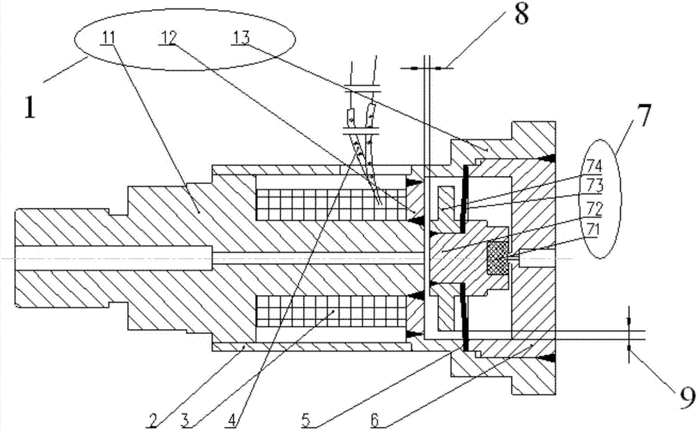
[0025] like figure 1 As shown, it is a schematic diagram of the magnetic circuit structure of the frictionless proportional valve of the present invention. A magnetic circuit structure of the frictionless proportional valve includes a valve body assembly 1, an external magnet 2, a coil 3, a lead wire 4, a gasket 5, a valve seat 6, Armature assembly 7.

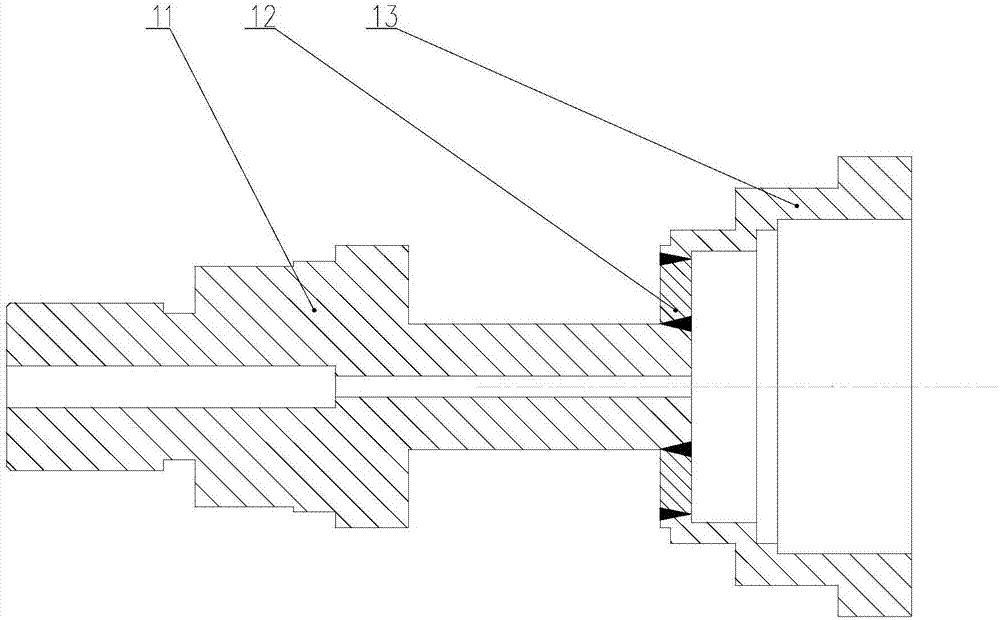
[0026] like figure 2 As shown, the valve body assembly 1 includes an inlet joint end 11, a magnetic isolation ring 12, and an outlet end 13; both the inlet joint end 11 and the outlet end 13 are of a rotary structure, and the magnetic isolation ring 12 is installed on the inlet joint end 11. and installed in the port of the outlet port 13, they are connected together by welding; the inlet joint end 11 has a through hole along the axis, and communicates with the inner cavity of the outlet port 13. The valve body as...


PUM


Abstract

The invention discloses a frictionless proportional valve magnetic circuit structure. According to a miniature proportional solenoid valve, the characteristic that a magnetic material B-H (magnetic flux density-magnetic induction intensity) curve is small in slope when being in a low-magnetic-flux-density area, in other words, the electromagnetic force is low as the current is increased is utilized, and a novel proportional valve magnetic circuit based on a large magnetic flux leakage technique is proposed. The frictionless proportional valve magnetic circuit structure is different from a traditional proportional valve magnetic circuit structure, the large-magnetic-flux-leakage magnetic circuit is utilized, frictionless movement of a valve is completely achieved, the proportional precision is improved, and the reliability of the valve is improved; and the dependence of the proportional valve on the machining precision of a boot-shaped part is further lowered, and the proportional valve can have better batch consistency. The structure can be used for proportional flow control of microfluid and can also provide proportional displacement output.

Description

technical field [0001] The invention relates to a proportional valve magnetic circuit structure. Background technique [0002] In the field of micro-flow proportional control, the proportional solenoid valve magnetic circuit, as a proportional actuator, has the advantages of convenient operation and simple control, and is a widely used driving method. The essence of the proportional valve is to make the electromagnetic force insensitive to displacement, but only proportional to the driving voltage or current, so that it is balanced with the spring force acting on the valve core. However, the traditional proportional electromagnetic magnetic circuit uses the method of bypass flux leakage to reduce the increase speed of electromagnetic force with the increase of current or voltage, so as to achieve the purpose of proportional control by balancing with the spring force. This structure makes the moving armature spool The gap with the bypass of the magnetic circuit is small, and...

Claims


Application Information

Patent Timeline
Patent Type & Authority Applications(China)
IPC IPC(8): F16K31/06
CPCF16K31/0675
Inventor 汪旭东陈君张榛高晨光关威龙军宋新河李恒建王焕春
Owner BEIJING INST OF CONTROL ENG
Learn More