
Gas charging apparatus for lighter

The technology of an inflatable device and a lighter is applied in the direction of combustion ignition, igniter with fuel, combustion method, etc., which can solve problems such as insufficient production efficiency, achieve convenient operation, reduce defective rate, and save time and effort when switching models

Active Publication Date: 2017-11-24
BENXI FENGHE LIGHTER
View PDF12 Cites 0 Cited by
  • Summary
  • Abstract
  • Description
  • Claims
  • Application Information

AI Technical Summary

Problems solved by technology

The production efficiency of this device is insufficient

Method used


Image

  • Gas charging apparatus for lighter
  • Gas charging apparatus for lighter
  • Gas charging apparatus for lighter

Examples


Embodiment 1

[0031] In order to make the technical means, creative features, goals and effects achieved by the present invention easy to understand, the present invention will be further described below in conjunction with specific embodiments.

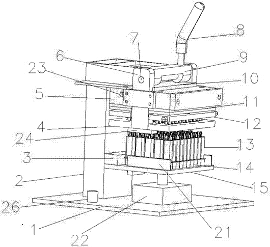
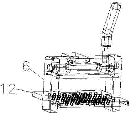
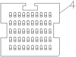
[0032] Such as Figure 1 to Figure 14 As shown, a lighter inflating device includes an ejector device, a needle raising device, an inflator device, a base plate 1 and a bracket 2, the base plate 1 and the bracket 2 are fixed together, and the ejector device includes a cylinder 22, a product pallet 15. Process plate 14, Y-axis limit block 3, X-axis limit block 21 and slide plate 20, the Y-axis limit block 3 and X-axis limit block 21 are connected to the top of the product pallet 15, and the process The disc 14 is placed on the top of the product pallet 15, the Y-axis limit block 3 and the product pallet 15 are slidably connected with the slide plate 20, and the needle raising device includes a positioning plate 4, a needle raising board 12, and a n...

Embodiment 2

[0034] Such as Figure 1 to Figure 15As shown, a lighter inflating device includes an ejector device, a needle raising device, an inflator device, a base plate 1 and a bracket 2, the base plate 1 and the bracket 2 are fixed together, and the ejector device includes a cylinder 22, a product pallet 15. Process plate 14, Y-axis limit block 3, X-axis limit block 21 and slide plate 20, the Y-axis limit block 3 and X-axis limit block 21 are connected to the top of the product pallet 15, and the process The disc 14 is placed on the top of the product pallet 15, the Y-axis limit block 3 and the product pallet 15 are slidably connected with the slide plate 20, and the needle raising device includes a positioning plate 4, a needle raising board 12, and a needle raising tube 18 , pull rod 6 and eccentric needle lifting rotor 9, the bottom of the needle lifting tube 18 is slidably connected with a gourd mouth 19, the needle lifting plate 12 is clipped together with the pull rod 6, and the...


PUM


Abstract

The invention discloses a gas charging apparatus for a lighter and relates to the technical field of manufacture of lighters. The gas charging apparatus comprises an ejecting device, a pin lifting device, a gas charging device, a bottom plate and a support. The ejecting device comprises a cylinder, a product carrier plate, a process disc, a Y-axial limiter, an X-axial limiter and a sliding plate. The pin lifting device comprises a positioning plate, a pin lifting plate, a pin lifting tube, a pull rod and an eccentric lift rotor. The gas charging device comprises a cavity plate, gas charging pins and an AB plate; the lateral side of the cavity plate is also provided with a gas inlet that is connected with a gas incoming pipe. The gas charging apparatus is simple in structure and convenient to operate, is suitable for independent operation by a single operator, allows ejection and pin lifting travels to be accurately controlled, and allows gas charging quantity to be precisely controlled, so that reject ratio of a charging procedure is effectively decreased; through alarming of an alarm and a flow controller, the gas charging quantity is under control, waste is avoided, and major safety accidents due to gas leakage are avoided; just after a process disc, a Y-axial positioner and a positioning plate for a corresponding product are renewed, the gas charging apparatus may adapt to various types of lighters and is widely applicable.

Description

technical field [0001] The invention relates to the technical field of lighter manufacturing, in particular to a lighter charging device. Background technique [0002] Lighter is an ignition tool commonly used by people in daily life. There are many types of lighters. Generally, butane gas is filled inside them. Since butane gas is a flammable and explosive gas, safety factors need to be considered when filling the lighter. Therefore, electrical components cannot be used for control. The traditional lighter production process adopts a single inflation mode, which has extremely low work efficiency, uneven gas volume, and unstable product quality. [0003] Chinese patent application number 201110029109.4 discloses a lighter inflator, including a frame, [0004] The frame is sequentially provided with a top mechanism, a lock needle mechanism, an inflation mechanism and an inflation cylinder for driving the inflation mechanism from bottom to top; The locking pin cylinder; the...

Claims


Application Information

Patent Timeline
Patent Type & Authority Applications(China)
IPC IPC(8): F23Q2/52
CPCF23Q2/52
Inventor 徐绍博
Owner BENXI FENGHE LIGHTER
Learn More