
Gun field rapid laser gun-calibrating instrument

A gun calibration and laser technology, which is applied in the field of military weapons and equipment, can solve the problems of not adapting to real-time calibration, cumbersome preparation work, and long distance between calibration guns, and achieves the effect of low requirements, fast calibration speed, and close site distance.

Pending Publication Date: 2017-11-24
JIANGJI MINKE IND COMPANY LIMITED JILIN CITY
View PDF7 Cites 5 Cited by
  • Summary
  • Abstract
  • Description
  • Claims
  • Application Information

AI Technical Summary

Problems solved by technology

[0002] The artillery of the combat troops should be calibrated before firing on the ground. At present, there is no national standard for the calibration method of various artillery in our army. Generally, the traditional aiming point method is adopted, that is, the firing pin of the artillery is removed, and the firing pin is aimed at from the firing pin hole. Method, the calibration distance needs to be more than 1000 meters. Due to the limitation of the site, the calibration distance is long, the accuracy guarantee is poor, the preparation work before the calibration is cumbersome, the entire calibration time is as long as 3-5 hours, and it is affected by mountain obstacles and bad weather. , sometimes it cannot be done, and it is not suitable for real-time calibration of artillery by modern informationized troops on the battlefield

Method used


Image

  • Gun field rapid laser gun-calibrating instrument
  • Gun field rapid laser gun-calibrating instrument

Examples


Embodiment Construction

[0011] Specific implementation plan

[0012] The specific embodiments of the present invention will be further described below in conjunction with the accompanying drawings and embodiments. The following embodiments are only used to illustrate the technical solutions of the present invention more clearly, and cannot be used to limit the protection scope of the present invention.

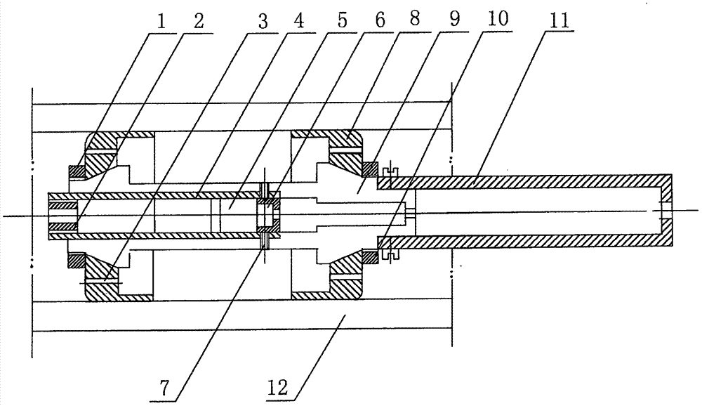
[0013] The purpose of the present invention is to solve the deficiencies of the prior art, and to design a rapid on-site laser gun calibration device for artillery, which consists of a laser calibration device and a gun calibration target, and is characterized in that: the laser calibration device includes: 1 rear nut , 2 top wires, 3 rear elastic positioning clamps, 4 sleeves, 5 laser collimator tubes, 6 gratings, 7 adjusting screws, 8 front elastic positioning clamps, 9 body, 10 front nuts, 11 handles, 12 barrels. Connection relationship: the front end of the laser collimator 5 is fixedly connected to t...


PUM


Abstract

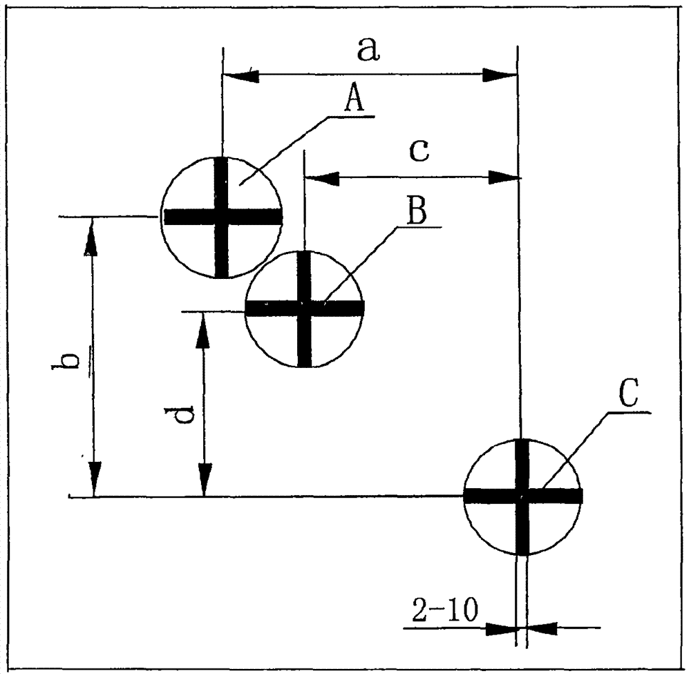
The invention relates to a gun field rapid laser gun-calibrating instrument, and belongs to military weapon technologies. The gun field rapid laser gun-calibrating instrument is mainly used for calibrating a gun. The gun field rapid laser gun-calibrating instrument is characterized in that the gun field rapid laser gun-calibrating instrument is composed of a laser calibration device and a gun-calibrating target. The laser calibration device comprises a body, a laser tube, a grating, a spring positioning clamp, an adjusting screw, a handle and the like, and is installed in a gun bore, and the laser axis is parallel to and consistent with the gun bore axis; the three cross curves of a panoramic mirror cross curve A, a direct-aiming mirror cross curve B and a gun bore axis cross curve C are arranged on the gun-calibrating target, the gun-calibrating target is arranged on the position which is about 50 meters away from the front portion of a gun muzzle, and the height of the gun-calibrating target is close to the height of a firing line; in the gun-calibrating process, firstly a laser light spot is aligned with the center of the gun bore axis cross curve C, then a direct-aiming mirror axis is aligned with the direct-aiming mirror cross curve B, a panoramic mirror axis is aligned with the panoramic mirror cross curve A, and gun calibrating is completed within ten minutes; and compared with an existing used gun-calibrating point aiming method of the army, the field needs to be close, the gun-calibrating speed is high, the accuracy degree is high, all-weather gun calibrating is achieved, and the gun field rapid laser gun-calibrating instrument can better adapt to the requirement for real-time gun calibrating in the army under the condition of informatization.

Description

Technical field [0001] The invention belongs to the technical field of military weapons and equipment, and is a gun calibration device, in particular to a field fast laser gun calibration device for artillery, which is mainly used for artillery such as howitzers, cannons, howitzers and tank guns. Background technique [0002] The artillery of combat troops should be calibrated before being fired on the ground. At present, there is no national standard for the calibration method of various artillery in our country. Generally, the traditional aiming point method is used, which is to remove the firing pin of the artillery and aim from the pin hole. Method, the gun calibration distance needs to be more than 1000 meters, due to site restrictions, the gun calibration distance is long, the accuracy guarantee is poor, the preparation work before the gun calibration is cumbersome, the entire gun calibration time is up to 3-5 hours, and it is affected by mountain obstacles and bad weather ...

Claims


Application Information

Patent Timeline
Patent Type & Authority Applications(China)
IPC IPC(8): F41G3/32F41F1/00
CPCF41F1/00F41G3/32
Inventor 徐长江许胜潘庚许治德刘泓佚段桂茹王峰
Owner JIANGJI MINKE IND COMPANY LIMITED JILIN CITY
Learn More