Guide assembly as well as vertical loading device and method

A technology of guiding components and vertical loading, which is applied in the direction of measuring devices, applying stable tension/pressure to test material strength, instruments, etc., and can solve problems such as inability to avoid lateral force, time and labor, and test failure. Achieve the effects of reducing the labor intensity of adjustment and assembly, avoiding deflection, and improving work efficiency

Active Publication Date: 2017-11-24
CRRC QISHUYAN INSTITUTE CO LTD
View PDF7 Cites 1 Cited by
  • Summary
  • Abstract
  • Description
  • Claims
  • Application Information

AI Technical Summary

Problems solved by technology

When using the actuator to do the vertical test with large load and large displacement, since the two ends of the actuator are movable spherical joints, the original test method cannot avoid the lateral force. In the vertical test, it i

Method used


Image

  • Guide assembly as well as vertical loading device and method
  • Guide assembly as well as vertical loading device and method
  • Guide assembly as well as vertical loading device and method

Examples


no. 1 example

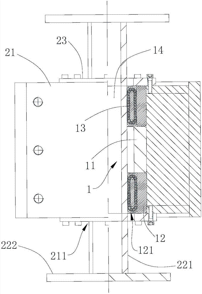
[0033] Please refer to figure 1 , the embodiment of the present invention provides a guide assembly 1 for installation on the guide beam 21 and for vertical loading, including at least one first annular sleeve 11, at least two second annular sleeves 12 and a plurality of linear roller bearings 13.

[0034] In this embodiment, the guide assembly 1 is used to prevent lateral force when the test piece is vertically loaded, and is used together with the guide beam for vertical loading test of the test piece. The guide assembly 1 includes two kinds of annular sleeves, the first annular sleeve 11 and the second annular sleeve 12, the two annular sleeves are superimposed on all, the two annular sleeves are coaxially arranged and form a guide hole 14 for passing through the loading mandrel, The first annular sleeve 11 is located between two adjacent second annular sleeves 12, and the inner surface of the second annular sleeve 12 is provided with a vertically arranged groove 121 (the ...

no. 2 example

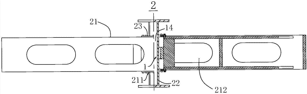
[0049] Please refer to figure 1 and figure 2 As shown, this embodiment provides a vertical loading device 2, including a guide beam 21, at least one loading mandrel 22 and at least one guide assembly 1 provided in the first embodiment.

[0050] In this embodiment, the guide beam 21 plays the role of fixing the guide assembly 1, the guide assembly 1 is installed in the guide beam 21, the loading mandrel 22 is passed through the guide hole 14, and the connection between the loading mandrel 22 and the linear roller bearing 13 There is a gap between them, the loading mandrel 22 can move along the axial direction of the guide hole 14, and the actuator acts on the loading mandrel 22 vertically, effectively avoiding the deflection of the loading mandrel 22 caused by the lateral force, and avoiding adjustment and assembly.

[0051] The specific structure and mutual positional relationship of each component of the vertical loading device 2 will be described in detail below.

[0052]...

no. 3 example

[0065] After research, the researchers found that the vertical loading device 2 provided by the present invention, on the basis of the above-mentioned second embodiment, can also make the following optional other structural solutions, which are specifically described as follows:

[0066] The gap between the loading mandrel 22 and the linear roller bearing 13 is 0.25 mm. When the gap between the loading mandrel 22 and the linear roller bearing 13 is 0.25 mm, the loading device (such as an actuator) is loaded on the loading mandrel 22 The vertical load on the test piece can be effectively transferred to the test piece, and the lateral force can be prevented.


PUM


Abstract

The invention relates to a guide assembly as well as a vertical loading device and method and belongs to the technical field of vertical loading test devices. The guide assembly comprises a first annular sleeve, second annular sleeves and linear roller bearings, wherein the first annular sleeve is located between the two adjacent second annular sleeves, the first annular sleeve and the second annular sleeves are coaxially arranged, a guide hole allowing penetration of a loading mandrel is formed, a plurality of grooves are formed in the inner surfaces of the second annular sleeves and extend in the axial directions of the second annular sleeves, and the linear roller bearings are arranged in the grooves, in one-to-one correspondence with the grooves and in clearance fit with the loading mandrel. By means of the vertical loading device equipped with the guide assembly, deflection of the loading mandrel due to lateral force is avoided effectively; with adoption of the vertical loading method, vertical load can be transferred effectively, the lateral force is prevented, high load and large-displacement loading of an actuator can be realized, test precision is high, and demands of various vertical loading tests can be met.

Description

technical field [0001] The invention relates to the technical field of vertical loading test devices, in particular to a guide assembly, a vertical loading device and a method. Background technique [0002] With the continuous improvement of test technology and test equipment, more and more products need to do vertical tests of large load and large displacement. When using the actuator to do the vertical test with large load and large displacement, since the two ends of the actuator are movable spherical joints, the original test method cannot avoid the lateral force. In the vertical test, it is easy to cause ball joints. The rotation of the hinge leads to the instability of the entire loading system. The light ones have to be reinstalled and debugged again, which takes a lot of time and labor; the heavy ones make the test invalid. Contents of the invention [0003] The purpose of the present invention is to solve the above problems and provide a guide assembly that can ...

Claims


Application Information

Patent Timeline
IPC IPC(8): G01N3/08
CPCG01N3/08G01N2203/0019G01N2203/0032
Inventor 吴特朱汉朝魏嘉杰王伟洋杨火顺张旻昌
Owner CRRC QISHUYAN INSTITUTE CO LTD
Why Eureka
Try Eureka