
Multi-joint flaw detecting and positioning device for bridge pipeline welding joints

A technology for welding joints and positioning devices, which is applied to measuring devices, material analysis using wave/particle radiation, instruments, etc., can solve the problems of small use range, lower flaw detection quality, and lower work efficiency, so as to increase the use range, The effect of improving the quality of flaw detection and improving work efficiency

Inactive Publication Date: 2017-11-24
洛阳高昌机电科技有限公司
View PDF8 Cites 1 Cited by
  • Summary
  • Abstract
  • Description
  • Claims
  • Application Information

AI Technical Summary

Problems solved by technology

[0003] The length of the support arm on the multi-section flaw detection machine for the existing bridge pipeline welded joints is fixed, so that only one diameter of pipeline can be used for flaw detection, and the scope of use is small. When there is an obstacle, it is impossible to pass through, which reduces work efficiency. The cameras on the multi-section flaw detection machine used for the welded joints of bridges and pipelines are all fixed by bolts, which often makes the camera appear dead angle, and cannot fully record the positional relationship between the radiation source and the weld seam, reducing the flaw detection. quality

Method used


Image

  • Multi-joint flaw detecting and positioning device for bridge pipeline welding joints
  • Multi-joint flaw detecting and positioning device for bridge pipeline welding joints
  • Multi-joint flaw detecting and positioning device for bridge pipeline welding joints

Examples


Embodiment Construction

[0019] In order to make the technical means, creative features, goals and effects achieved by the present invention easy to understand, the present invention will be further described below in conjunction with specific embodiments.

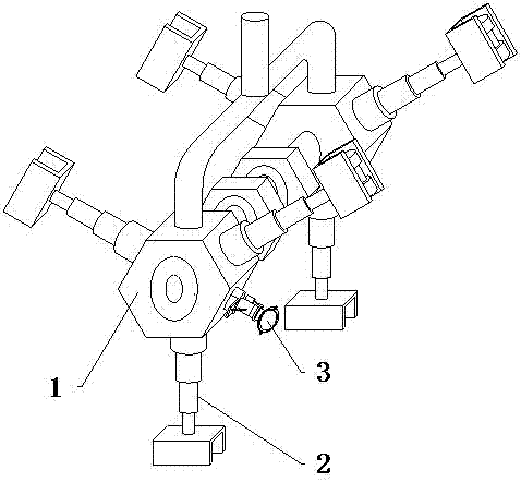
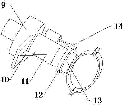
[0020] see Figure 1-Figure 3 , the present invention provides a technical solution: a multi-section flaw detection and positioning device for welded joints of bridge pipelines, including a cavity-type end 1, a walking mechanism 2 and an auxiliary mechanism 3, and the outer end of the cavity-type end 1 is provided with a walking Mechanism 2, an auxiliary mechanism 3 is installed at the right end of the cavity type end 1.

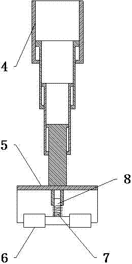
[0021] The traveling mechanism 2 includes a multi-section telescopic rod 4, a U-shaped mounting frame 5, a pulley 6, a spring 7 and a slide rod 8, the outer end of the multi-section telescopic rod 4 is provided with a U-shaped mounting frame 5, and the inside of the U-shaped mounting frame 5 is provided with a pulley 6. The inn...


PUM


Abstract

The invention provides a multi-joint flaw detecting and positioning device for bridge pipeline welding joints. The device comprises multi-joint telescopic rods, U-shaped mounting frames, pulleys, springs, slide rods, a stud, an electric telescoping cylinder, a moving rod, an annular gear, a rotating rod and a transmission gear. The pulleys are arranged in the U-shaped mounting frames which are arranged at outer ends of the multi-joint telescopic rods, and the springs are mounted on the slide rods which are arranged at inner ends of the pulleys. Extension length of the pulleys can be adjusted, a telescoping function is achieved, and crossing over weld joints or obstacles can be realized. The rotating rod is arranged at the right end of the moving rod which is arranged at the right end of the stud, the transmission gear is arranged at the upper end of the annular gear which is mounted on the rotating rod, and the electric telescoping cylinder is arranged at the front end of the moving rod. A camera is rotational and can be conveniently adjusted in angle. The multi-joint flaw detecting and positioning device has advantages of convenience in use, expansion of an application range, improvement of flaw detection quality and high reliability.

Description

technical field [0001] The invention relates to a multi-section flaw detection and positioning device for welded joints of bridge pipelines, which belongs to the technical field of bridge construction. Background technique [0002] A bridge refers to a building erected on rivers, lakes and seas to enable the smooth passage of vehicles and pedestrians. It is called a bridge. A bridge is generally composed of a superstructure, a substructure, a support and ancillary structures. The superstructure is also called a bridge span structure, which is the main structure for crossing obstacles; the substructure includes abutments, piers and foundations; Or the force transmission device installed at the supporting place of the bridge abutment; the auxiliary structures refer to the bridge head plate, conical slope protection, revetment, diversion works, etc. During the bridge construction process, it is often necessary to bury the relevant pipelines. [0003] The length of the support ...

Claims


Application Information

Patent Timeline
Patent Type & Authority Applications(China)
IPC IPC(8): G01N23/00
CPCG01N23/00G01N2223/321G01N2223/629G01N2223/646
Inventor 张义勇
Owner 洛阳高昌机电科技有限公司
Learn More