Compressor transfer device for refrigeration equipment
A transfer device and refrigeration equipment technology, applied in the direction of hoisting equipment braking device, hoisting device, transportation and packaging, etc., can solve the problems of low flexibility and inconvenient use, and achieve increased flexibility, improved stability, and reduced collisions Effect
- Summary
- Abstract
- Description
- Claims
- Application Information
AI Technical Summary
Problems solved by technology
Method used
Image
Examples
Embodiment 1
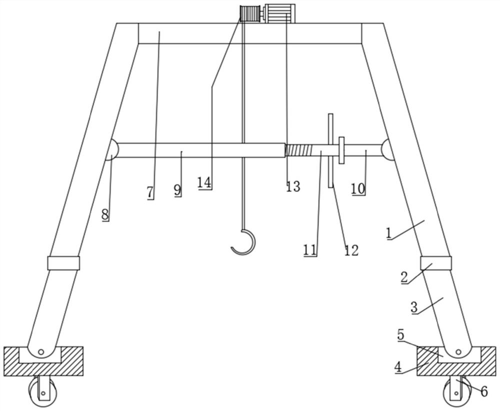
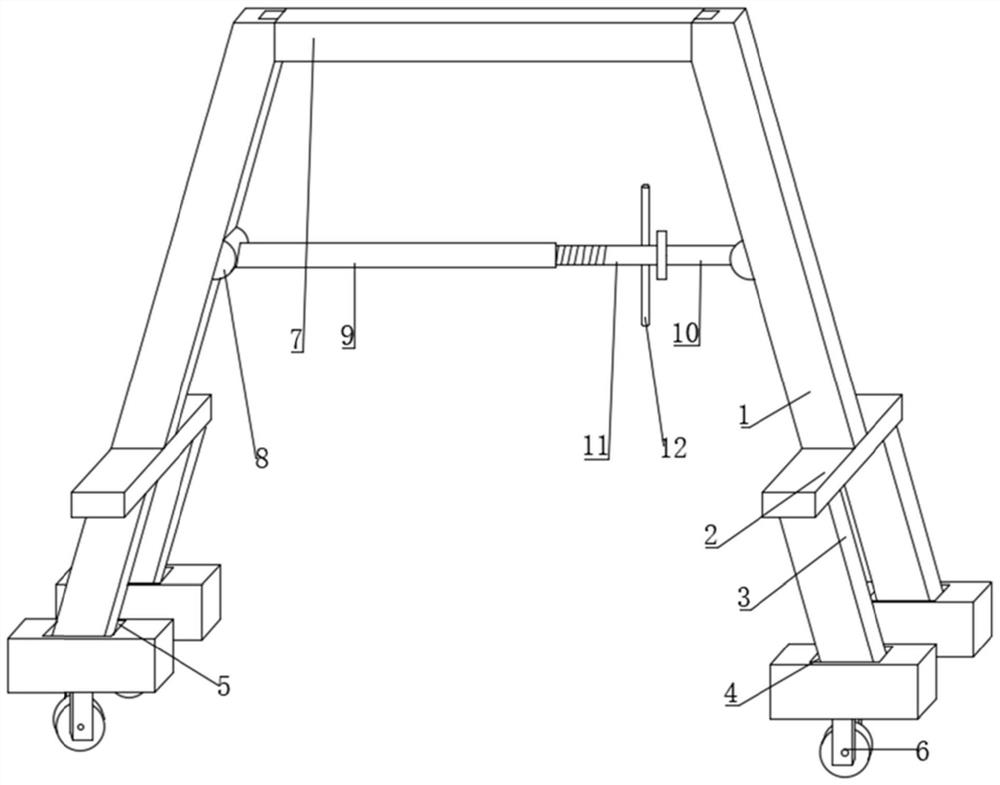
[0023] refer to Figure 1-2 , a compressor transfer device for refrigeration equipment, including a support mechanism and a suspension mechanism, the support mechanism includes two first support rods 1, the bottom of the first support rod 1 is fixed with a mounting plate 2 by bolts, and the bottom of the mounting plate 2 passes through Bolts are fixed with two second struts 3 distributed front and rear, the bottom of the second strut 3 is provided with a fixed seat 4, and the top of the fixed seat 4 is provided with a movable groove 5, and the second strut 3 and the inner wall of the movable groove 5 pass through a bearing Rotational connection, the bottom of the fixed base 4 is fixed with a moving wheel 6 by bolts, the top of the two first poles 1 is rotationally connected with the same crossbar 7 through bearings, the inner side of the first pole 1 is fixed with a mounting block 8 by bolts, two The inner side of the mounting block 8 is respectively connected to the bushing 9...
Embodiment 2
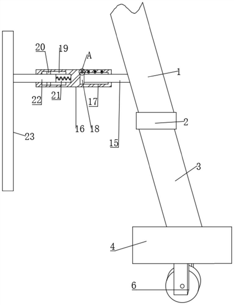
[0027] refer to Figure 1-4 , a compressor transfer device for refrigeration equipment, the inner side of the first support rod 1 is fixed with a third support rod 15 by bolts, the inner side of the third support rod 15 is provided with a connecting rod 16, and the inner side of the connecting rod 16 is provided with a mounting groove 21. A first spring is fixed in the slot 21 by bolts, an inner rod 22 is fixed on the inner side of the first spring by bolts, a baffle plate 23 is fixed on the inner side of the inner rod 22 by bolts, and a drawer is provided between the connecting rod 16 and the third support rod 15. Mechanism, the top and bottom of the installation groove 21 are provided with a limit groove 19, and the limit block 20 is slidably connected in the limit groove 19, and the two limit blocks 20 are respectively fixedly connected with the corresponding positions of the inner rod 22. There is a drawing groove 17 on the outside, and a moving block 18 is slidably connec...
PUM
 Abstract
Description
Claims
Application Information
 - R&D
- Intellectual Property
- Life Sciences
- Materials
- Tech Scout
- Unparalleled Data Quality
- Higher Quality Content
- 60% Fewer Hallucinations
Browse by: Latest US Patents, China's latest patents, Technical Efficacy Thesaurus, Application Domain, Technology Topic, Popular Technical Reports.
© 2025 PatSnap. All rights reserved.Legal|Privacy policy|Modern Slavery Act Transparency Statement|Sitemap|About US| Contact US: help@patsnap.com


