A rotary switch and its control method

A technology of knob switch and control method, which is applied in the direction of electric switch, program control, computer control, etc.

Active Publication Date: 2021-08-20
HUIZHOU CONMO MEDICAL TECH CO LTD
View PDF8 Cites 0 Cited by
  • Summary
  • Abstract
  • Description
  • Claims
  • Application Information

AI Technical Summary

Problems solved by technology

[0002] Existing knob switches use tact switches or dome buttons to realize functions. One button usually corresponds to 1 to 2 functions. It also brings certain challenges to the appearance design of the product

Method used


Image

  • A rotary switch and its control method
  • A rotary switch and its control method
  • A rotary switch and its control method

Examples


Embodiment Construction

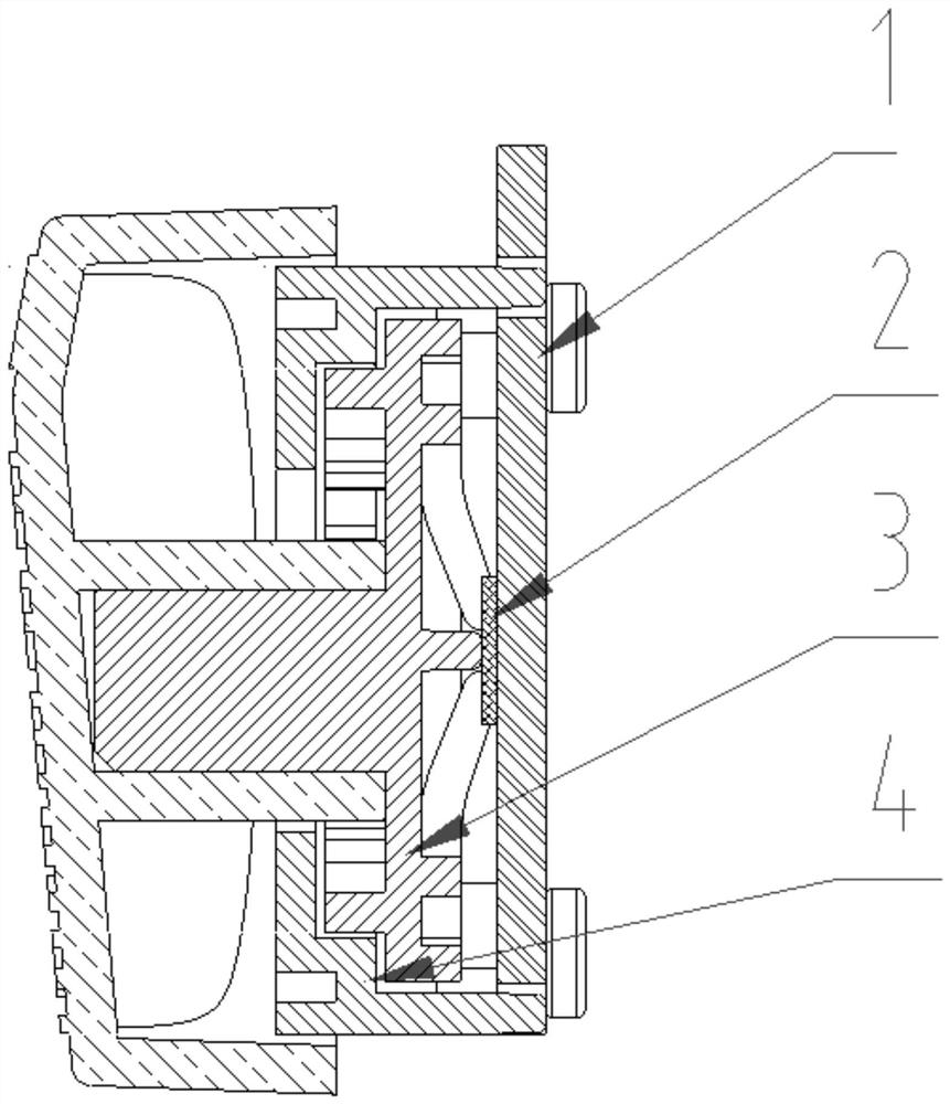
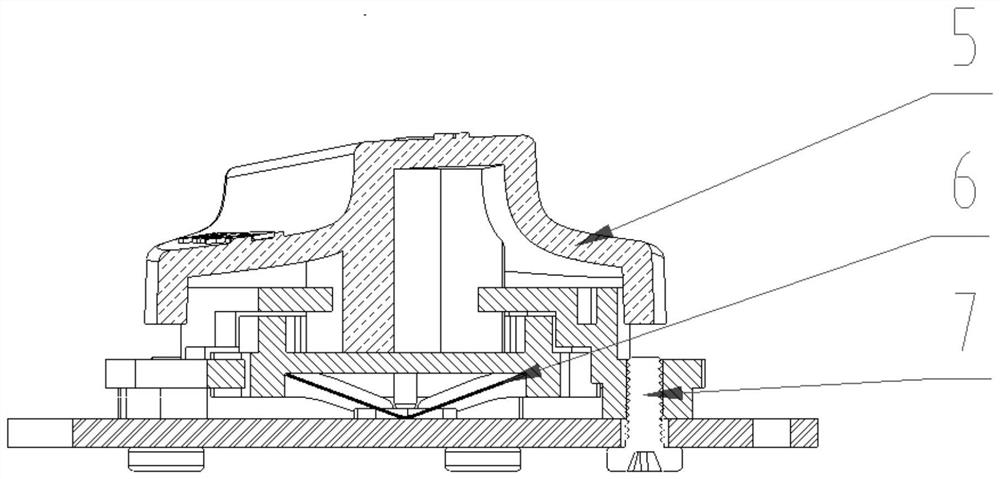
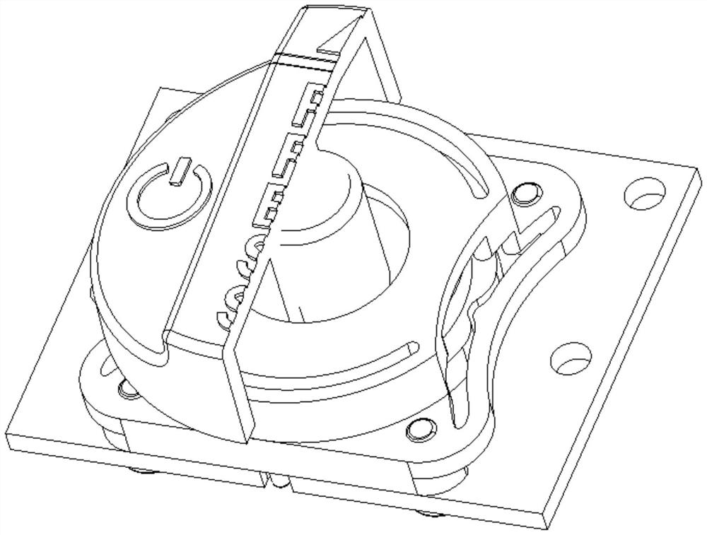
[0024] like Figure 1-4 As shown, a rotary switch includes a PCB board 1, a metal dome 2, a first rotating mechanism 3, a second rotating mechanism 4, a rotating cap 5, a contact piece 6, and a screw 7, and the second rotating mechanism 4 passes through the screw 7 is fixed on the PCB board 1, the second rotating mechanism 4 is connected to the first rotating mechanism 3, one end of the first rotating mechanism 3 is connected to the rotating cap 5, and the other end of the first rotating mechanism 3 is connected to the contact piece 6, the contact piece 6 is connected to the dome 2, and the dome 2 is connected to the PCB board 1.

[0025] In this embodiment, the PCB board 1 is provided with a plurality of output terminals connected to the domes 2 .

[0026] like Figure 5 As shown, in this embodiment, the output terminals are all connected to the MCU controller.

[0027] like Image 6 , 7 As shown, a rotary switch control method includes the following steps:

[0028] Ste...


PUM


Abstract

The invention discloses a rotary switch and a control method thereof, comprising a PCB board, a dome, a first rotating mechanism, a second rotating mechanism, a rotating cap, a contact piece, and screws, and the second rotating mechanism is fixed on the PCB board through screws , the second rotating mechanism is connected with the first rotating mechanism, one end of the first rotating mechanism is connected with the rotating cap, the other end of the first rotating mechanism is connected with the contact sheet, the contact sheet is connected with the dome, and the dome is connected with the PCB board catch. The rotary switch of the present invention realizes different gears when rotating through the plastic structure, and the plastic of the rotating part rotates to different positions to drive the contact piece to trigger different functions. At the same time, long press and short press the knob can also achieve different controls. The principle is that when the knob is in different positions or pressed, it will output a level signal and transmit it to the main control MCU. The main control MCU will process the level signal after receiving it, so as to complete the corresponding control. The operation is simple and easy, and the design of the rotary cap is rich and varied.

Description

technical field [0001] The invention relates to the technical field of electronic switches, in particular to a rotary switch and a control method thereof. Background technique [0002] Existing knob switches use tact switches or dome buttons to realize functions. One button usually corresponds to 1 to 2 functions. It also brings certain challenges to the appearance design of the product. Contents of the invention [0003] In view of the above-mentioned defects in the prior art, the technical problem to be solved by the present invention is to provide a rotary switch and its control method. The rotary knob can be rotated to different positions to trigger different functions, and the functions can also be realized by pressing the rotary knob, so that multiple functions can be concentrated in one Simple and easy operation on one knob. [0004] In order to achieve the above object, the present invention provides a rotary switch, comprising a PCB board, a dome, a first rotati...

Claims


Application Information

Patent Timeline
Patent Type & Authority Patents(China)
IPC IPC(8): H01H25/06G05B19/042
CPCG05B19/0423H01H25/06
Inventor 齐玮齐瑛
Owner HUIZHOU CONMO MEDICAL TECH CO LTD
Why Eureka
Try Eureka