

Field-weakening control method for permanent magnet synchronous motor
A permanent magnet synchronous motor and field-weakening control technology, which is applied in motor control, motor generator control, AC motor control, etc., can solve the problems of easy instability of motor vibration, reduce motor vibration, and reduce current ripple. wave, increasing the stability effect
- Summary
- Abstract
- Description
- Claims
- Application Information
AI Technical Summary
Problems solved by technology
Method used
Image

Examples
Embodiment Construction
[0014] The present invention will be further described below in conjunction with the accompanying drawings.
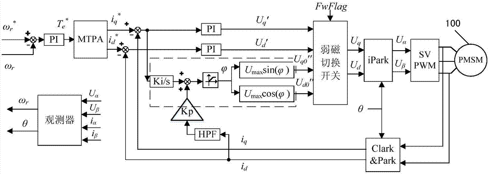
[0015] figure 2 A control principle block diagram of a field weakening control method for a permanent magnet synchronous motor according to an embodiment of the present invention is shown. Please refer to figure 2 , according to an embodiment of the present invention, a permanent magnet synchronous motor field weakening control method and figure 1 Compared with the existing permanent magnet synchronous motor field weakening control method shown in , the main difference is that the addition of i q high frequency compensation, that is figure 2 The part shown in the dotted box.
[0016] Specifically, the field weakening control method for a permanent magnet synchronous motor according to an embodiment of the present invention includes the following steps:
[0017] Step a. Obtain the d-axis output voltage U through no-current-loop field-weakening control d0 "and q...
PUM
 Abstract
Description
Claims
Application Information