
Eureka
For R&D, Eureka makes reading and utilizing patents & technical documents easy.
Eureka AIR
Designed for self-driven R&D workflows. Generate viable solutions, solve complex R&D challenges, empower your innovation with AI.

Eureka Materials
Designed for material experts only. Revolutionize your material R&D, from search, analyze, to developing new materials.

TechResearch
Generate reliable direction feasibility study reports for your R&D in just a few steps.

TechSeek
Discover and master advanced knowledge NOW. Basics, ideas, possibilities, all at once.

TechMind
As an expert in R&D Theories, TechMind can generates customized viable solutions instantly.

TechRisk
Analyze your overall solution with one click, know your potential R&D risks in advance.

TechMonitor
Get weekly tech updates, stay abreast of the latest tech innovations and key insights.
Movable glue barrel
A technology of rubber barrels and barrels, which is applied in the direction of anti-rot containers, mixers with rotating containers, containers, etc., can solve the problems of sedimentation and agglomeration, and achieve convenient movement, stable support, and prevention of sedimentation and agglomeration of glue. Effect
- Summary
- Abstract
- Description
- Claims
- Application Information
AI Technical Summary
Problems solved by technology
Method used
Image

Examples
Embodiment 1
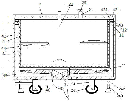
[0015] Embodiment one, see figure 1 , a movable glue barrel, including a barrel body 1, a barrel cover 2, an outer rotor motor 3 and a glue storage tank 4.
[0016] Barrel 1 is circular. An inner convex ring 11 is provided on the upper end of the inner peripheral surface of the barrel body 1 . The inner convex ring 11 extends along the circumferential direction of the barrel body 1. On the upper end surface of the inner convex ring 11, a plurality of balls 12 are arranged along the circumferential direction of the barrel body. The bottom of the bucket body 1 is provided with several supporting foot mounting frames 24 . The supporting foot installation frame 24 is connected with a traveling wheel 241 and a transverse support rod 242 . The horizontal support bar 242 is threadedly connected with a support foot 243 . When it is necessary to move the staving 1, turn the supporting legs 243 to move the supporting legs 243 up to lose the supporting effect. At this moment, the pre...
Embodiment 2
[0021] Embodiment two, the difference with embodiment one is:
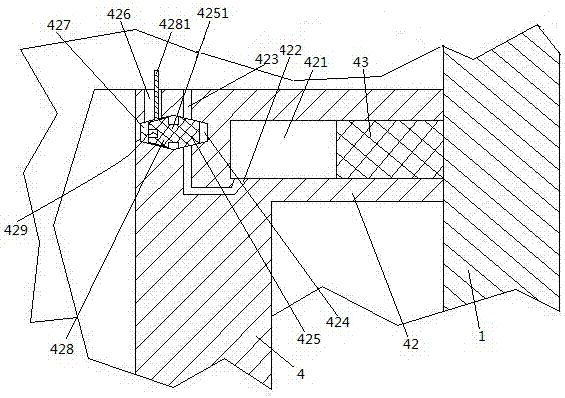
[0022] see figure 2 , A water collecting bucket 422 is provided on the lower side wall of the annular groove 421 . The water collecting bucket 422 is the lowest point of the lower side wall of the water collecting bucket 422 , that is, the liquid in various parts in the annular groove 421 can gather in the water collecting bucket 422 under the action of its own weight. The water collecting bucket 422 is provided with a liquid outlet hole 423 drawn from the upper end surface of the glue storage tank 4 . The liquid outlet hole 423 is provided with a first sealing hole 424 . The first sealing hole 424 is a tapered hole. The axial direction of the first sealing hole 424 extends not only in the horizontal direction but also in the radial direction of the rubber storage tank. The end of the first sealing hole 424 away from the axis of the rubber storage tank is a small diameter end. A first tapered sealing head 425...
PUM
 Abstract
Description
Claims
Application Information
 - R&D Engineer
- R&D Manager
- IP Professional
- Industry Leading Data Capabilities
- Powerful AI technology
- Patent DNA Extraction
Browse by: Latest US Patents, China's latest patents, Technical Efficacy Thesaurus, Application Domain, Technology Topic, Popular Technical Reports.
© 2024 PatSnap. All rights reserved.Legal|Privacy policy|Modern Slavery Act Transparency Statement|Sitemap|About US| Contact US: help@patsnap.com