Manual transmission interlock cage and manual transmission

A technology of manual transmission and limit hole, which is applied in transmission control, components with teeth, belts/chains/gears, etc. It can solve the problems of damage to the transmission body, time-consuming and labor-intensive effects, and wear of limit grooves, and achieve reliable Good performance, long service life, avoid the effect of swinging back and forth

Inactive Publication Date: 2017-11-28
ZHEJIANG WANGLIYANG TRANMISSION CO LTD
View PDF5 Cites 2 Cited by
  • Summary
  • Abstract
  • Description
  • Claims
  • Application Information

AI Technical Summary

Problems solved by technology

In this case, the method of using the limit groove and the interlock cage body to cooperate with the limit is time-consuming and laborious and the effect is not good
[0010] Therefore, in view of the inaccurate limit of the existing interlock cage in the aluminum shift mechanism housing of the manual transmission, the long-term use causes the limit groove of the aluminum select shift mechanism housing to wear, causing the interlock cage to be in front of and behind the shift fork groove. Swing, the interlock effect is reduced, and there is a risk of damage to the transmission body and a decrease in comfort when selecting and shifting. It is necessary to carry out research and innovation on the existing interlock cage

Method used


Image

  • Manual transmission interlock cage and manual transmission
  • Manual transmission interlock cage and manual transmission
  • Manual transmission interlock cage and manual transmission

Examples


Embodiment Construction

[0027] In order to make the object, technical solution and advantages of the present invention clearer, the present invention will be further described in detail below in conjunction with the accompanying drawings and embodiments. It should be understood that the specific embodiments described here are only used to explain the present invention, not to limit the present invention.

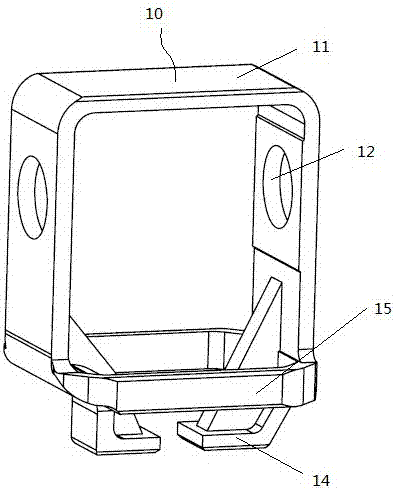
[0028] Such as image 3 As shown, the manual transmission interlock cage 10 includes an interlock cage body 11 and a shift shaft through hole 12 located on the interlock cage body 11, and the top of the interlock cage 10 is provided with a limiting groove or a limiting hole 13, so The limiting slot or hole 13 is elongated, and its length direction is consistent with the axial direction of the shift shaft through hole 12 .

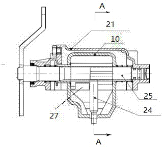
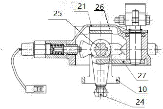
[0029] Such as Figure 4a with Figure 4b As shown, the manual transmission includes a gear selection mechanism housing 21, a shift dial 24, and also includes a limit block 2...


PUM


Abstract

The invention belongs to the field of automobile transmissions and particularly relates to a manual transmission interlock cage and a manual transmission. The interlock cage is provided with a limiting slot or limiting hole in the top, the limiting slot or limiting hole is elongated, the length direction of the limiting slot or limiting hole is consistent with the axial direction of shifting shaft through holes, the length of the limiting slot or limiting hole is greater than or equal to a selection travel of a shifting head, and a limiting block arranged on a shifting mechanism case and capable of relatively moving in the limiting slot or limiting hole along the length direction of the limiting slot or limiting hole is extended into the limiting slot or limiting hole. The limiting slot or limiting hole and the limiting block have high machining precision and high strength and hardness, a fitting clearance between the limiting slot or limiting hole and a limiting pin is small, and the limiting pin experiences small sliding loss in the limiting slot or limiting hole; therefore, it is ensured that the interlock cage may be kept vertical constantly, and it is avoided that excessive manual shifting force leads to damage of the shifting mechanism case and affects the gear interlocking function.

Description

technical field [0001] The invention belongs to the field of automobile transmissions, and in particular relates to a manual transmission interlock cage and a transmission. Background technique [0002] The interlock cage is mainly used in the gear selection mechanism of manual transmission. The position of the interlock cage in the gear selection mechanism is mainly set on the outside of the shift dial, and is sleeved on the shift shaft together with the shift dial. And can move axially on the shift shaft together with the shift paddle. The shift paddle is splined with the shift shaft and can rotate together with the shift shaft. The interlock cage is empty on the shift shaft. At the same time, the top of the interlock cage is embedded in the aluminum shift mechanism housing. In the limiting groove, prevent the interlock cage from swinging back and forth. [0003] The main function of the interlock cage is that when the transmission selects and shifts gears, the rotation ...

Claims


Application Information

Patent Timeline
Patent Type & Authority Applications(China)
IPC IPC(8): F16H63/34F16H63/30
CPCF16H63/30F16H63/3408
Inventor 李欣黄翔乔湘鹤叶伟飞孙皝杨硕温晓平梅状张建旭吉康胜李华
Owner ZHEJIANG WANGLIYANG TRANMISSION CO LTD
Why Eureka
Try Eureka