
Capacitor with standby capacitor

A technology of capacitors and circuits, applied in the field of capacitors, can solve problems such as time-consuming, increase safety hazards, fire or explosion, etc., and achieve the effects of saving maintenance and replacement time, ensuring normal operation, and short power-off time

Pending Publication Date: 2017-11-28
CHIZHOU RONGDA ELECTRIC CO LTD
View PDF4 Cites 4 Cited by
  • Summary
  • Abstract
  • Description
  • Claims
  • Application Information

AI Technical Summary

Problems solved by technology

[0003] Metallized film capacitors, especially large-capacity capacitors, are in high-current charging and discharging operations, especially in high-temperature working environments. Due to the chemical reaction, electrochemical reaction and high-temperature evaporation inside the capacitor, gas will be generated inside the supercapacitor. There will be more and more gas in the sealed state, which will gradually increase the pressure inside the capacitor, and eventually cause the explosion-proof groove on the capacitor shell to rupture, which will not only damage the capacitor, but also increase potential safety hazards, which may easily cause fire or explosion major safety accidents
[0004] In addition, when the capacitor is damaged and needs to be replaced, it is necessary to cut off the power first, then discharge the capacitor to ensure safety, and then replace it with a new capacitor. This kind of safety operation procedure is very time-consuming. During the period of power failure, Capacitor bank not working properly

Method used


Image

  • Capacitor with standby capacitor

Examples


Embodiment 1

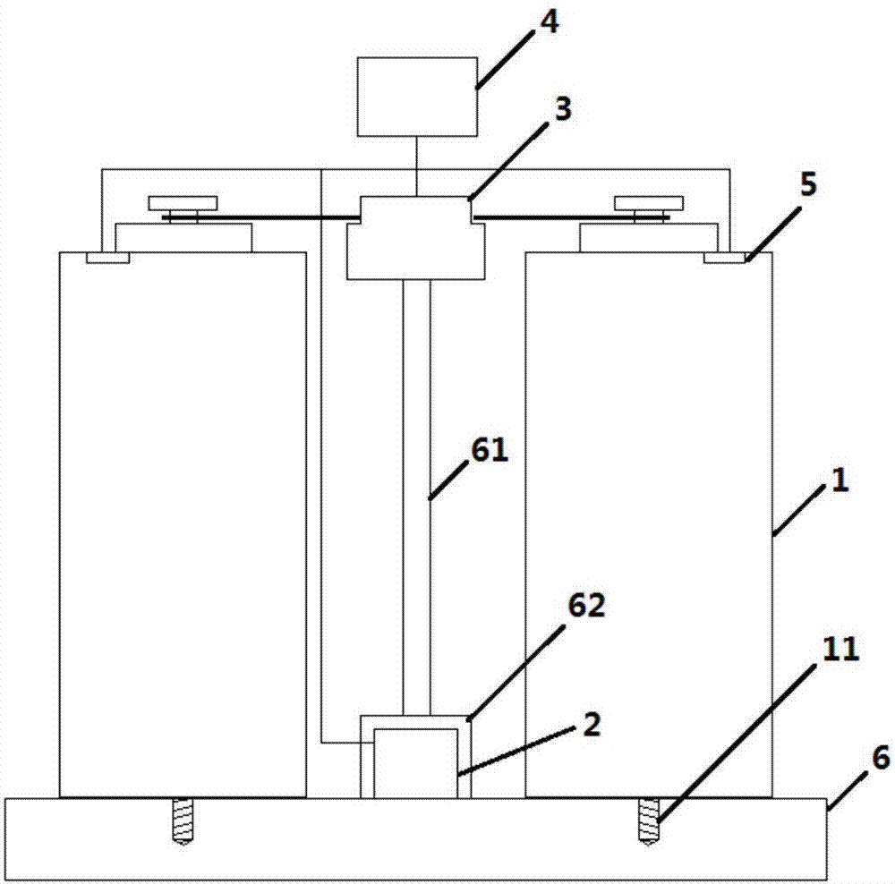
[0016] A capacitor with a backup capacitor, including a capacitor 1, a controller 2, a circuit switcher 3, a circuit breaker 4, and a pressure sensor 5, the number of the capacitors 2 is two, and the two capacitors 2 are installed side by side on the same base 6 Above, the two sets of terminals of the circuit switcher 3 are respectively connected to the terminals of the two capacitors 2 one by one. After the circuit breaker 4 is connected in series with the circuit switcher 3, the circuit breaker 4 is connected to the main circuit, and the controller 2 is connected to The circuit breaker 4 is connected to the circuit switcher 3, and the number of the pressure sensors 5 is two, and the two pressure sensors 5 are respectively arranged inside the two capacitors 2, and the pressure sensors 5 are connected to the controller 2 through signal lines.

[0017] Further, a pressure sensor 5 is arranged inside the capacitor 1, and the pressure sensor 5 is fixed on the bottom surface of the...


PUM


Abstract

The invention discloses a capacitor with a standby capacitor. The capacitor comprises two sub-capacitors, a controller, a circuit switching device, a circuit breaker and pressure sensors. Two sub-capacitors are arranged parallelly on the same base. Two sets of terminals of the circuit switching device are connected with the terminals of the two sub-capacitors in one-to-one correspondence. After the circuit breaker is serially connected with the circuit switching device, the circuit breaker is connected with a main circuit. The controller is connected with the circuit breaker and the circuit switching device. Two pressure sensors are respectively arranged in the two sub-capacitors. The pressure sensors are connected with the controller through signal wires. The capacitor has an explosion-proof function. Furthermore when a fault of one sub-capacitor occurs, automatic power supply stoppage and switching to the other standby sub-capacitor are performed. Then automatic energization is performed. Then the faulted capacitor is manually changed for standby in the next time. The capacitor provided by the invention has advantages of saving maintenance and changing time, and ensuring normal operation of the equipment.

Description

technical field [0001] The invention relates to the field of capacitors, in particular to a capacitor with a backup capacitor. Background technique [0002] Due to the advantages of high power density, long cycle life and fast charging speed, metallized film capacitors have broad application prospects in various fields such as mobile communications, electric tools, solar power generation, wind power generation, information technology and electric vehicles. [0003] Metallized film capacitors, especially large-capacity capacitors, are in high-current charging and discharging operations, especially in high-temperature working environments. Due to the chemical reaction, electrochemical reaction and high-temperature evaporation inside the capacitor, gas will be generated inside the supercapacitor. There will be more and more gas in the sealed state, which will gradually increase the pressure inside the capacitor, and eventually cause the explosion-proof groove on the capacitor s...

Claims


Application Information

Patent Timeline
Patent Type & Authority Applications(China)
IPC IPC(8): H01G4/33H01G4/38H01G4/40H01G4/002
CPCH01G4/002H01G4/33H01G4/38H01G4/40
Inventor 郑国祥
Owner CHIZHOU RONGDA ELECTRIC CO LTD
Learn More