Accumulator
A technology for accumulators and pressure vessels, which is applied in the direction of accumulator devices, actuator accumulators, shock absorbers, etc., and can solve the problems of unstable installation state of the intermediate ring 590 and failure to achieve stability, etc., to achieve Mounting status, impact mitigation effect
- Summary
- Abstract
- Description
- Claims
- Application Information
AI Technical Summary
Problems solved by technology
Method used
Image

Examples
Embodiment 1
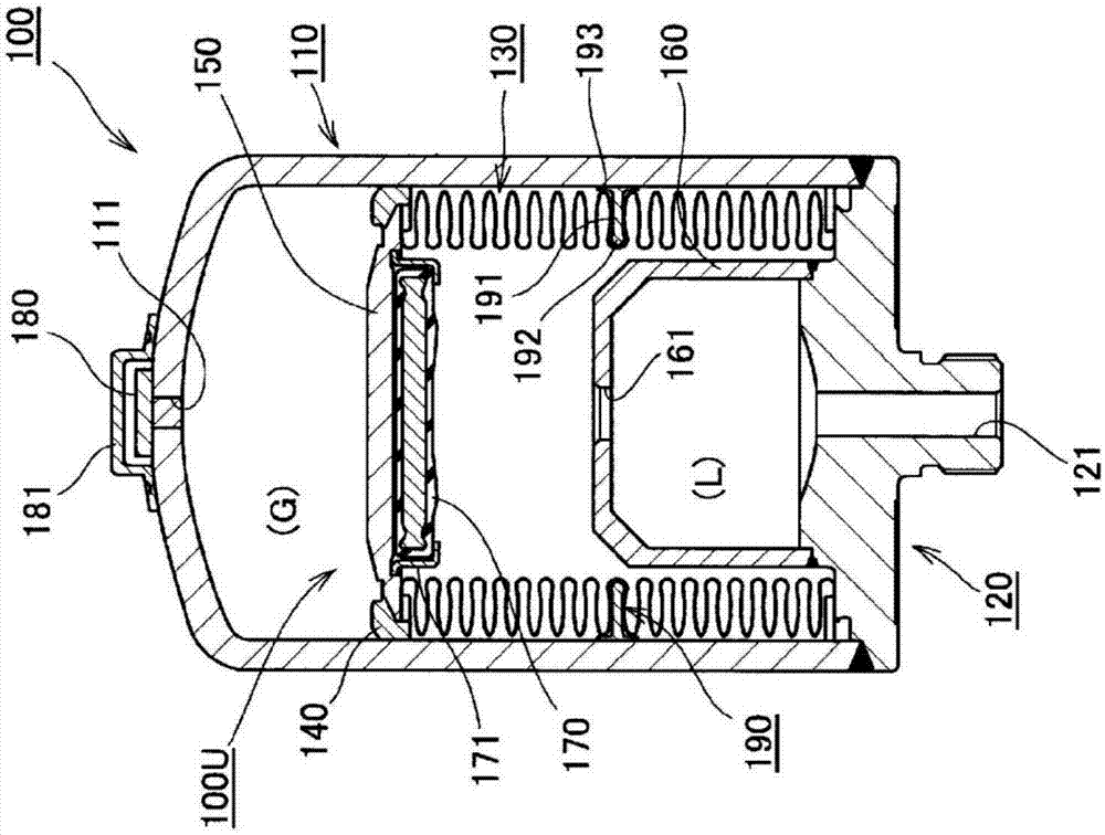
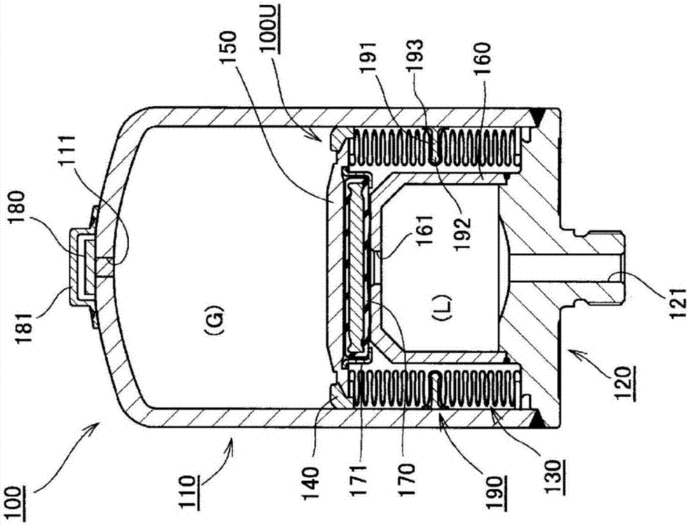
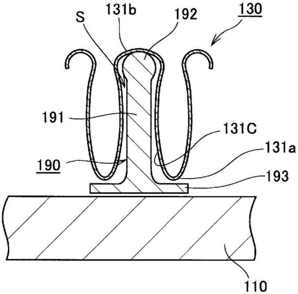
[0047] refer to Figure 1 to Figure 5 , the accumulator according to Embodiment 1 of the present invention will be described. figure 1 and figure 2 is a schematic cross-sectional view of the accumulator of Embodiment 1 of the present invention, figure 1 Indicates the stretched state of the metal bellows, figure 2 It shows the state of the metal bellows shrinking. image 3 It is a partially enlarged schematic cross-sectional view of an accumulator according to Embodiment 1 of the present invention, and is an enlarged cross-sectional view near a vibration-damping member. Figure 4 It is a plan view of the damping member of Example 1 of the present invention. Figure 5 It is a side view of the damping member according to Example 1 of the present invention, and is a view of the damping member viewed from the outer peripheral surface side.
[0048]
[0049] In particular, refer to figure 1 and figure 2, the overall structure of the accumulator according to Embodiment...
Embodiment 2
[0067] Figure 6 Example 2 of the present invention is shown. In this embodiment, a configuration in which the structure of the damping member is different from that of the first embodiment is shown. The other configurations and functions are the same as those in Embodiment 1, so the same components are given the same reference numerals and their descriptions are omitted.
[0068] Figure 6 is a schematic cross-sectional view of an accumulator according to Example 2 of the present invention, showing a state in which the metal bellows is stretched. The vibration damping member 190X of this embodiment has the main body part 191 and the fitted part 192 similarly to the vibration damping member 190 of the said 1st Embodiment. However, unlike the vibration damping member 190 of the first embodiment, the vibration damping member 190X of the present embodiment does not have the guide portion 193 . In the vibration damping member 190X of the present embodiment, only the radially o...
Embodiment 3
[0070] Figure 7 Example 3 of the present invention is shown. In this embodiment, a structure in which the installation position of the damping member is different from that of the first embodiment is shown. The other configurations and functions are the same as those in Embodiment 1, so the same components are given the same reference numerals and their descriptions are omitted.
[0071] Figure 7 is a schematic cross-sectional view of an accumulator according to Example 3 of the present invention, showing a state in which the metal bellows is stretched. In the first embodiment described above, the configuration in which the damping member 190 is provided at the center position in the axial direction of the metal bellows 130 is shown. However, it is effective to install the vibration damping member 190 at the position where the vibration in the direction perpendicular to the axial direction is the largest on the metal bellows 130 . In this way, the position where the vibr...
PUM
 Abstract
Description
Claims
Application Information
 - R&D
- Intellectual Property
- Life Sciences
- Materials
- Tech Scout
- Unparalleled Data Quality
- Higher Quality Content
- 60% Fewer Hallucinations
Browse by: Latest US Patents, China's latest patents, Technical Efficacy Thesaurus, Application Domain, Technology Topic, Popular Technical Reports.
© 2025 PatSnap. All rights reserved.Legal|Privacy policy|Modern Slavery Act Transparency Statement|Sitemap|About US| Contact US: help@patsnap.com