Sealing ring

A sealing ring and dynamic pressure technology, which is applied to the sealing of the engine, engine components, mechanical equipment, etc., can solve the problems of fluid leakage and increased leakage, and achieve the effects of suppressing leakage and reducing rotational torque

Active Publication Date: 2017-11-28
NOK CORP
View PDF11 Cites 2 Cited by
  • Summary
  • Abstract
  • Description
  • Claims
  • Application Information

AI Technical Summary

Problems solved by technology

However, with this technique, since the fluid to be sealed will leak from the groove, the amount of leakage may increase

Method used


Image

  • Sealing ring
  • Sealing ring
  • Sealing ring

Examples


Embodiment approach 1

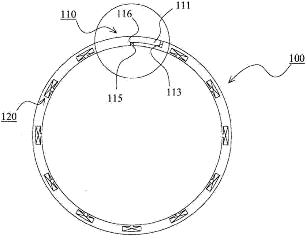
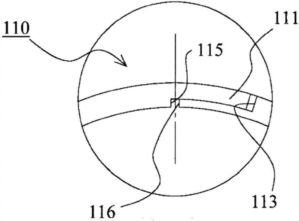
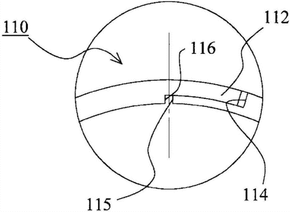
[0121] refer to Figure 1 to Figure 6 The seal ring according to Embodiment 1 of the present invention will be described. figure 1 It is a side view of the seal ring according to Embodiment 1 of the present invention. figure 2 It is a partial enlarged view of the side view of the seal ring according to Embodiment 1 of the present invention, and is figure 1 A magnified view of the portion surrounded by a circle in . image 3 It is a partial enlarged view of the side view of the seal ring according to Embodiment 1 of the present invention, viewed from the opposite side figure 1 A magnified view of the portion surrounded by a circle in . Figure 4 It is a partially enlarged view of the seal ring according to Embodiment 1 of the present invention viewed from the outer peripheral surface side, and is viewed from the outer peripheral surface side figure 1 A magnified view of the portion surrounded by a circle in . Figure 5 It is a partial enlarged view of the sealing ring acc...

Embodiment 1

[0137] refer to Figure 7 ~ Figure 9 The groove portion 120 according to the first embodiment will be described. Figure 7 It is a partial enlarged view of the side view of the seal ring according to Embodiment 1 of the present invention, and is an enlarged view of the vicinity where the groove portion 120 is provided. Figure 8 is a schematic cross-sectional view of the seal ring according to Embodiment 1 of the present invention, and is Figure 7 AA sectional view in . Figure 9 is a schematic cross-sectional view of the seal ring according to Embodiment 1 of the present invention, and is Figure 7 BB section view in .

[0138] As described in the above embodiment, the groove portion 120 is provided on the sliding surface side of the seal ring 100 . The groove part 120 involved in this embodiment consists of the first groove 121 extending in the circumferential direction and extending from the circumferential center of the first groove 121 to the inner peripheral surface...

Embodiment 2

[0145] Figure 10 Example 2 of the present invention is shown. This embodiment is a modified example of the above-mentioned first embodiment, and differs from the first embodiment in the arrangement area of ​​the dynamic pressure generating groove 121a and the foreign matter capturing groove 121b. Figure 10 It is a partial enlarged view of the side view of the seal ring according to Example 2 of the present invention, and is an enlarged view of the vicinity where the groove portion 120 is provided.

[0146] In the present embodiment, in the first groove 121, the dynamic pressure generating grooves 121a are respectively provided on both sides of the center in the circumferential direction. In addition, the pair of dynamic pressure generating grooves 121a is formed so as to gradually become shallower from the center side in the circumferential direction toward the ends in the circumferential direction. Although not shown in the present embodiment, the groove bottom of the pai...


PUM


Abstract

Provided is a sealing ring that suppresses leakage of a fluid to be sealed and that is capable of stably reducing rotational torque. A sliding surface side is provided with a groove portion (120) that comprises a first groove (121) extending in the circumferential direction and a second groove (122) that extends from a central position of the circumferential direction in the first groove (121) to an inner circumferential surface and that guides the fluid to be sealed into the first groove (121), characterized in that the first groove (121) comprises a groove for generating dynamic pressure (121a) formed such that the groove bottom is shallower in the end portions of the circumferential direction when compared to the center of the circumferential direction and a groove for capturing foreign objects (121b) capable of capturing foreign objects, the groove bottom of which is deeper than the groove bottom of the groove for generating dynamic pressure (121a), and in that the first groove (121) is provided in a position fitting into a sliding region that slides with respect to a side wall surface.

Description

technical field [0001] The invention relates to a sealing ring for sealing an annular gap between a shaft and a casing. Background technique [0002] In Automatic Transmission (AT) or Continuously Variable Transmission (CVT) for automobiles, etc., there is a sealing ring for sealing the annular gap between the relatively rotating shaft and the housing to maintain oil pressure. In recent years, due to the promotion of low fuel consumption as a countermeasure against environmental problems, the demand for reducing the rotational torque in the above-mentioned seal rings is increasing. Conventionally, a technique of providing a groove for introducing a fluid to be sealed to the sliding surface side of the seal ring to generate dynamic pressure is known (see Reference 1). However, with this technology, when foreign matter is contained in the fluid to be sealed, the foreign matter will be stuck in the groove, which will not only reduce the effect of dynamic pressure and result in...

Claims


Application Information

Patent Timeline
Patent Type & Authority Applications(China)
IPC IPC(8): F16J15/18
CPCF16J15/164F16J15/3272F16J15/441
Inventor 宫崎真以子酒井阳平吉村健一当间将太
Owner NOK CORP
Why Eureka
Try Eureka