
Electronic equipment

A technology of electronic equipment and terminals, applied in the field of electronic equipment, can solve problems such as damage to sealing performance

Active Publication Date: 2019-07-05
ORMON CORP
View PDF5 Cites 0 Cited by
  • Summary
  • Abstract
  • Description
  • Claims
  • Application Information

AI Technical Summary

Problems solved by technology

[0005] However, during electrical connection, the molten solder invades into the gap between the outer surface of the insulating base 3005 and the inner peripheral surface of the cover 51 due to capillary action, contacts the sealant 45, and damages the sealing performance.

Method used


Image

  • Electronic equipment
  • Electronic equipment
  • Electronic equipment

Examples


Embodiment Construction

[0057] refer to Figure 1 to Figure 19 Embodiments of the electronic device of the present invention will be described.

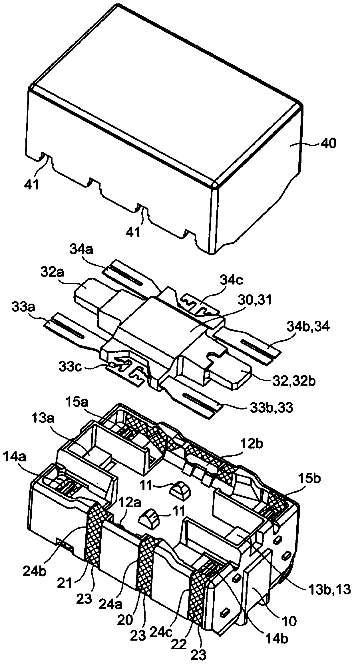
[0058] Such as Figure 1 to Figure 7 As shown, the first embodiment is applied to an electromagnetic relay, and has an insulating base 10 , a movable contact piece 30 , and a cover 40 .

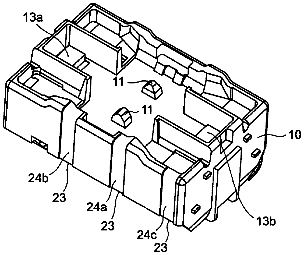
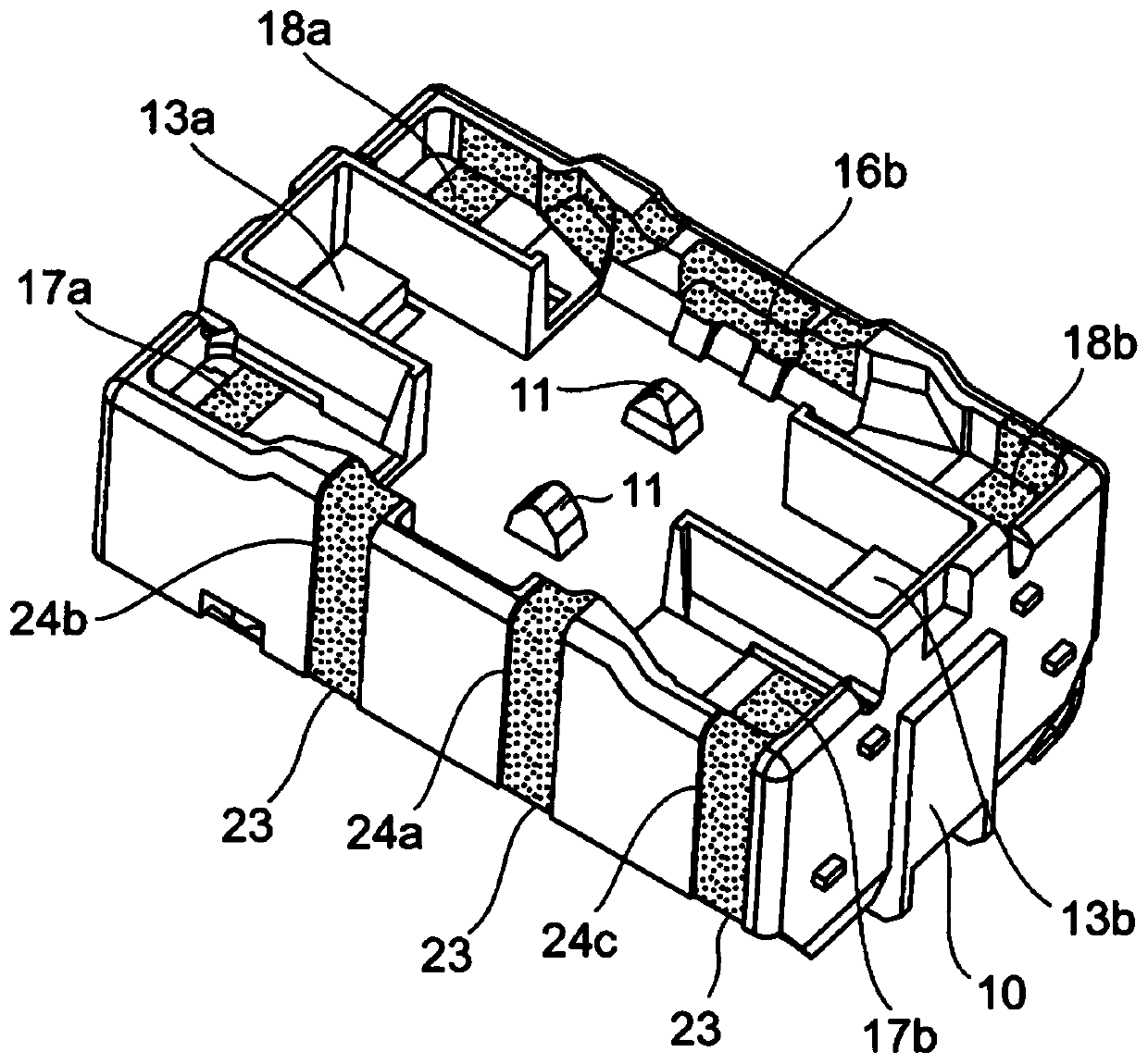
[0059] Such as figure 1As shown, the insulating base 10 is insert-molded with a gate-shaped cross-section iron core 13 wound with a coil (not shown), and its molding material contains basic polymer, filler and metal powder. Examples of the basic polymer include liquid crystal polymer (LCP) and polybutylene terephthalate (PBT). Furthermore, the insulating base 10 is provided with a pair of support protrusions 11, 11 protruding from the center of the bottom surface thereof. Common electrodes 12a, 12b are disposed on both sides of the supporting protrusions 11, 11. In addition, the magnetic pole portions 13a, 13b of the iron core 13 are exposed at positions facing each ...


PUM


Abstract

The invention provides an electronic device in which molten solder does not contact the sealing material and does not damage the sealing performance. Therefore, the electronic device of the present invention has: an insulating base (10) mounted on a printed circuit board (51); A common planar terminal (20) that conducts on the outer surface of the insulating base (10) and the edge of the bottom surface; fits with the insulating base (10) and connects the common planar terminal (20) A covering cover (40); a sealing material (50) sealing a gap between an outer surface of the insulating base (10) and an inner peripheral surface of the cover (40). A solder pool (23) is formed at a position surrounded by the common planar terminal (20) and the printed circuit board (51) on the edge of the bottom surface of the insulating base (10).

Description

technical field [0001] The present invention relates to electronic devices, and in particular, to electronic devices surface-mounted on printed substrates via solder. Background technique [0002] Conventionally, as an electronic device surface-mounted on a printed circuit board, there is, for example, a leadless surface-mount relay. The electromagnetic relay includes: a coil assembly having an iron core; a coil reel provided inside with a part of the iron core exposed; A coil wound on a coil reel; an armature assembly, which has an armature that makes one end of itself abut at least one end of the iron core, a movable contact spring that has at least one movable contact at the front end, and A supporting body composed of an insulator supporting the armature and the movable contact spring; an insulating base having at least one fixed contact opposite to the movable contact, a fixed contact terminal holding the fixed contact, and inside accommodating the coil assembly; a cov...

Claims


Application Information

Patent Timeline
Patent Type & Authority Patents(China)
IPC IPC(8): H01H9/02H01H45/04
CPCH01H50/043H01H51/229H01H2001/5888H01H50/023H01H50/047H01H50/14H05K1/181H05K2201/10053H05K2201/1078H05K2201/10803H05K2201/10931
Inventor 下田城毅阿部正章
Owner ORMON CORP
Learn More