Switchgear cabinet or rack for accommodating electrical energy stores, in particular batteries, and a corresponding switchgear cabinet assembly or rack assembly

A technology for electric accumulators and switch cabinets, which is applied in the field of switch cabinets or racks, and can solve the problems of not being able to accommodate electric accumulators, high construction costs, and occupying structural space

Inactive Publication Date: 2017-11-28
RITTALWERK RUDOLF LOH GMBH & CO KG
View PDF11 Cites 0 Cited by
  • Summary
  • Abstract
  • Description
  • Claims
  • Application Information

AI Technical Summary

Problems solved by technology

[0003] The known switchgear has the disadvantage that it is expensive to construct due to the use of a separate bottom for separating the wooden frame

Method used


Image

  • Switchgear cabinet or rack for accommodating electrical energy stores, in particular batteries, and a corresponding switchgear cabinet assembly or rack assembly
  • Switchgear cabinet or rack for accommodating electrical energy stores, in particular batteries, and a corresponding switchgear cabinet assembly or rack assembly
  • Switchgear cabinet or rack for accommodating electrical energy stores, in particular batteries, and a corresponding switchgear cabinet assembly or rack assembly

Examples


Embodiment Construction

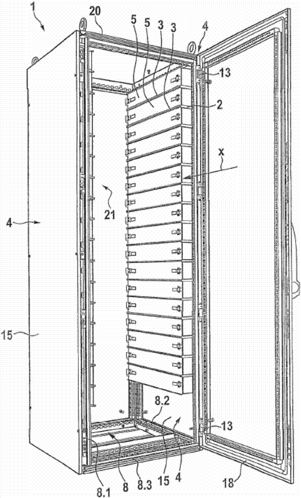
[0022] figure 1 A switchgear 1 according to an embodiment of the invention is shown. The switchgear 1 has a frame frame 8 formed by four vertical columns 8.1, four depth columns 8.2 and four width columns 8.3. At the eight corners of the frame frame 8, there are respectively a vertical column 8.1, a depth column 8.2 and a width column 8.3 which intersect at right angles. The frame frames are each covered with side pieces 15 on the opposite sides 4 . The frame rack 8 is covered on the bottom side by the bottom plate 19 , on the top side by the top element 20 and at the rear by the rear wall 21 . On the front side, the switch cabinet door 18 is pivotably fastened to the frame frame 8 by means of hinges.

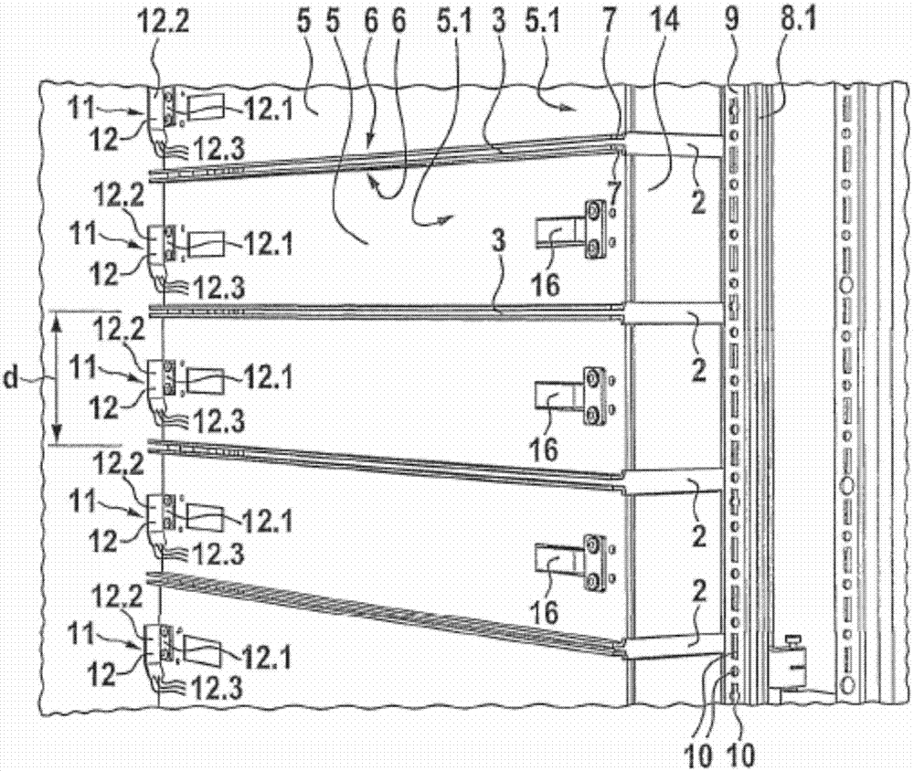
[0023] On the opposite sides 4 of the switchgear cabinet 1 , a plurality of mounting bases 5 are mounted on the inside on the side walls 15 , one above the other, respectively, on the inside, said mounting bases forming a plurality of accumulator inserts 2 with grooves 3 the...


PUM


Abstract

The invention relates to a switchgear cabinet or rack for accommodating electrical energy stores, in particular batteries, wherein the switchgear cabinet (1) or the rack comprises a plurality of superimposed energy storage inserts (2), characterized in that the energy storage inserts (2) are formed by a plurality of grooves (3), wherein the longitudinal direction and the direction of insertion (x) thereof extend in a depth direction of the switchgear cabinet (1) or rack, wherein a respective pair of the grooves (3) are directed toward one another on opposite sides (4) of the switchgear cabinet (1) or rack on the same vertical height and with their open longitudinal side. The invention further relates to a corresponding switchgear cabinet assembly or rack assembly.

Description

technical field [0001] The invention is based on a switch cabinet or rack for accommodating electrical energy accumulators, in particular accumulators, wherein the switch cabinet or rack has a plurality of accumulator inserts arranged on top of each other. Background technique [0002] Such a switchgear is disclosed, for example, in US8900737B2. The switchgear has a plurality of wooden frames separated from each other by a separating base, in which the electrical energy accumulators can be accommodated in each case. Similar switchgear cabinets are also disclosed in EP1462813A2, EP1355404B1, EP2731166A1, WO03 / 019703A1, WO2005 / 074097A2 and WO02 / 027817A1. [0003] The disclosed switchgear cabinet has the disadvantage that it is expensive to construct due to the use of a split bottom for separating the wooden frame, wherein the split bottom itself occupies a construction space inside the switch cabinet which cannot therefore be used for accommodating electricity. Accumulator. ...

Claims


Application Information

Patent Timeline
IPC IPC(8): H01M2/10H01M50/204H01M50/244H01M50/262
CPCH01M50/262H01M50/244H01M50/204Y02E60/10H01M50/20H01M10/42H05K7/18H05K5/04H02B1/301H02B1/32
Inventor 迈克尔·巴赫
Owner RITTALWERK RUDOLF LOH GMBH & CO KG
Why Eureka
Try Eureka