a lift shifter

A technology of positioner and limit block, which is applied in the directions of transportation and packaging, packaging, conveyor objects, etc., can solve the problems of complex structure, complicated program control and high maintenance cost of the lifting positioner, so as to reduce equipment failure points, The program control is simplified and the effect of ensuring safe production

Active Publication Date: 2019-03-29
刘云梦
View PDF5 Cites 0 Cited by
  • Summary
  • Abstract
  • Description
  • Claims
  • Application Information

AI Technical Summary

Problems solved by technology

[0002] The existing lifting positioner uses the cylinder to push the lock plate and press it to the lock block to realize the function of locking the equipment movement. Once the line body has an accident (such as: gas stop, sudden rupture of the trachea, etc.), the equipment will automatically Falling back, prone to production safety accidents
In addition, the existing lifting positioner has complex structure, high cost, many fault points, high maintenance cost, and complicated program control

Method used


Image

  • a lift shifter
  • a lift shifter
  • a lift shifter

Examples


Embodiment 1

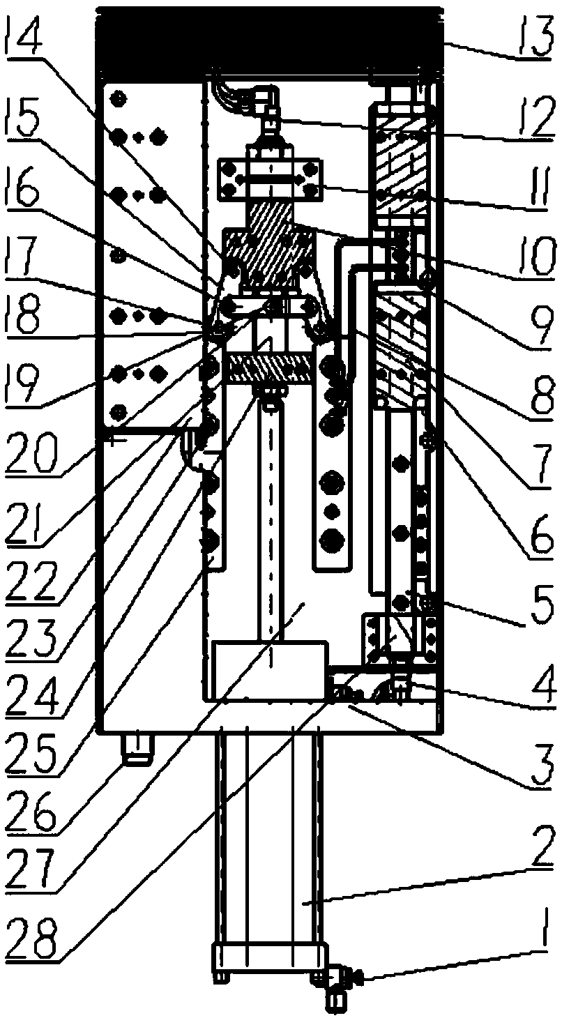
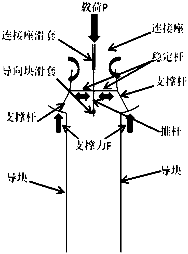
[0034] When the piston rod of the displacement cylinder 2 stretched out, the push rod 21 pushed one end of the stabilizing rod to move upward, and the other end of the stabilizing rod 20 pushed the supporting rod 15 to rotate clockwise around the hinge axis of the supporting rod 15 and the connecting seat 10. Driven by 15, the guide wheel 18 is supported on the guide surface of the guide block 25, the cylinder rod continues to move upward, and the push rod 21, the stabilizer rod 20 and the support rod 15 form a relatively fixed state and move upward together, thereby pushing the connecting seat 10 to drive the installation. Plate 22 moves upwards. When the guide wheel 18 reaches the buffer surface of the guide block 25, the support rod 15 rotates clockwise around the hinge shaft of the support rod 15 and the connecting seat 10 to the working position, the mounting plate 22 stops moving upward, and the active force of the load passes through the support rod 15 directly. It acts...


PUM


Abstract

The invention discloses a lifting positioner characterized by comprising a buffer self-locking device, a linear motion accuracy control device, a lubricating device, an antiskid device and a signal feedback device. According to the lifting positioner disclosed by the invention, the in-position buffering and self-locking functions are achieved through the mechanical structure characteristics. Under normal working conditions, the in-position buffering is finished automatically to avoid impact, so that the safety production is ensured; at the same time, the structure is optimized and simplified, and the manufacturing cost and fault points of equipment are reduced; and the maintenance cost of the equipment is reduced, and the program control is also simplified.

Description

technical field [0001] The invention relates to a control technology required to achieve safe production of lifting displacement in the production process of an automobile production line, in particular to a lifting displacement device. Background technique [0002] The existing lifting positioner uses the cylinder to push the lock plate and press it to the lock block to realize the function of locking the equipment movement. Once the line body has an accident (such as: gas stop, sudden rupture of the trachea, etc.), the equipment will automatically fall, prone to production safety accidents. In addition, the existing elevating positioner has complex structure, high cost, many fault points, high maintenance cost, and complicated program control. Contents of the invention [0003] The purpose of the present invention is to address the above problems, overcome the deficiencies of the prior art, and disclose a lifting positioner. For the defects of the existing lifting posit...

Claims


Application Information

Patent Timeline
Patent Type & Authority Patents(China)
IPC IPC(8): B65G47/74B65G43/00
CPCB65G43/00B65G47/74B65G2207/40
Inventor 刘云梦
Owner 刘云梦
Why Eureka
Try Eureka