Hydrate reservoir developing well group structure and method using geothermal energy

A technology of hydrate and geothermal energy, applied in the direction of mining fluid, earthwork drilling, wellbore/well components, etc., can solve the problems of large heat loss, low utilization efficiency, high cost, etc., to increase heat exchange efficiency and reduce heat injection Cost, EOR effect

Active Publication Date: 2017-12-01
CHINA UNIV OF PETROLEUM (EAST CHINA)
View PDF3 Cites 28 Cited by
  • Summary
  • Abstract
  • Description
  • Claims
  • Application Information

AI Technical Summary

Benefits of technology

This technology involves utilizing this type of resource from deeper drilling into underground rocks called thermal brine or water-based resources like geysers that are located near land where they produce hydrocarbons (oil) through evaporation over several thousand years ago. By selecting specific areas within these zones, there will be more efficient ways to use them while reducing costs associated with producing oil compared to traditional methods such as steam flooding.

Problems solved by technology

This patented describes different ways to improve the exploitation of geology's potential resource through creation of structures called well groups that contain vertical injector wells (VAP) within one common oil field basin. These techniques help reduce heat losses during drilling operations while also improving the overall performance of these structures. Additionally, this technology allows us to efficiently produce liquid fuels like shale oil at lower costs than current options due to its unique characteristics.

Method used


Image

  • Hydrate reservoir developing well group structure and method using geothermal energy

Examples


Embodiment Construction

[0015] The present invention will be further described below in conjunction with the accompanying drawings, but the implementation scope of the present invention is not limited.

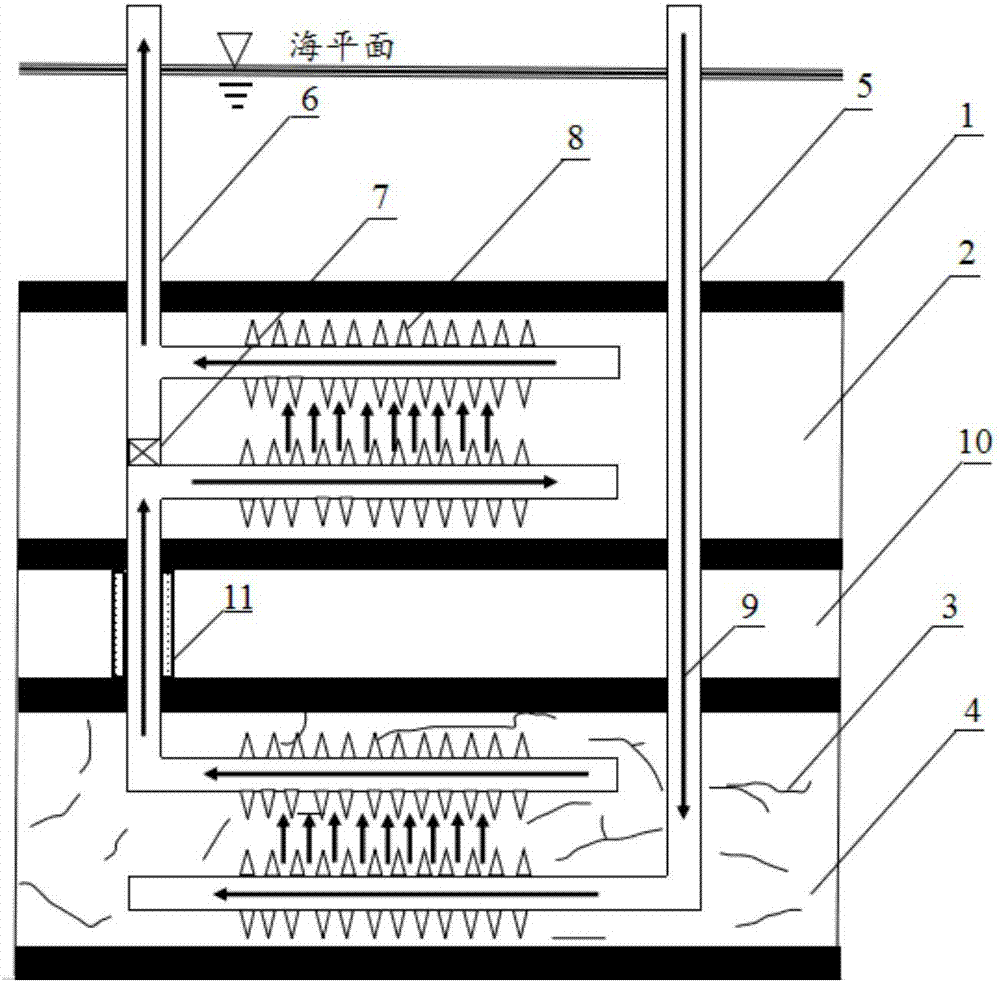
[0016] Such as figure 1 As shown, according to the geological structure conditions, the sea area where hydrate reservoir 2 exists and the hot dry rock reservoir 4 is developed under the hydrate reservoir 2 is selected as the measure area, in which the thickness of hydrate reservoir 2 is 15m, and the The average temperature is 160°C;

[0017] Such as figure 1 As shown, a horizontal injection well 5 and a comprehensive well 6 are drilled at sea level, wherein the horizontal injection well 5 runs through the hydrate reservoir 2 and extends to the lower hot dry rock reservoir 4 A horizontal well section with a length of 800m is generated by building a deflection at the position, and the comprehensive well 6 includes extending from the sea level to the gas hydrate reservoir 2 distance from the top Th...


PUM

PropertyMeasurementUnit
Thicknessaaaaaaaaaa
Lengthaaaaaaaaaa

Abstract

The invention discloses a hydrate reservoir developing well group structure and method using geothermal energy. The well group structure mainly comprises a horizontal injection well and a comprehensive well, wherein cold fluid is injected into the horizontal injection well, flows into a directional communication well section of the comprehensive well on the top after being heated by a hot dry rock reservoir, and flows upwards back to a hydrate reservoir, the heated fluid flows into the hydrate reservoir through a perforation section to provide energy for hydrate decomposition, and the mixed fluid of natural gas generated by decomposition and the injected fluid is extracted from a horizontal production well section of the comprehensive well on the top under the influence of gravity and pressure. According to the hydrate reservoir developing well group structure and method using the geothermal energy, heat of the hot dry rock reservoir is transmitted to the hydrate reservoir through heat transport fluid, at the same time, a plurality of horizontal well sections are chosen to improve the heat exchange efficiency, and deficiencies such as low heat utilization rate and high development cost of a traditional thermal excitation method are made up for. The hydrate reservoir developing well group structure using the geothermal energy has simple equipment and is convenient to operate, high in economic efficiency and capable of providing guidance for implementation of hydrate reservoir production increasing measures.

Description


Claims


Application Information

Patent Timeline
Owner CHINA UNIV OF PETROLEUM (EAST CHINA)
Why Eureka
Try Eureka