Flow control valve

A flow control valve and valve port technology, which is applied in the field of flow control valves for adjusting refrigerant flow, can solve the problems of easy occurrence and growth, refrigerant peeling, pressure changes, etc., and achieve smooth flow, reduced pressure loss, and suppressed pressure. effect of change

Active Publication Date: 2017-12-01
FUJIKOKI MFG CO LTD
View PDF7 Cites 2 Cited by
  • Summary
  • Abstract
  • Description
  • Claims
  • Application Information

AI Technical Summary

Problems solved by technology

[0005] Among the flow regulating valves 2 formed in such a way as to obtain equal percentage characteristics, such as Figure 5 As indicated by the bold arrow, when the flow direction of the refrigerant is from the valve chamber 6 to the valve port 15, the flow of the refrigerant along the curved surface 23 is prone to rapid pressure changes and refrigerant peeling when passing through the valve port 15. , vortex and cavitation are prone to occur and grow, while the problem of larger noise occurs

Method used


Image

  • Flow control valve
  • Flow control valve
  • Flow control valve

Examples


Embodiment Construction

[0035] Hereinafter, specific embodiments of the present invention will be described with reference to the drawings.

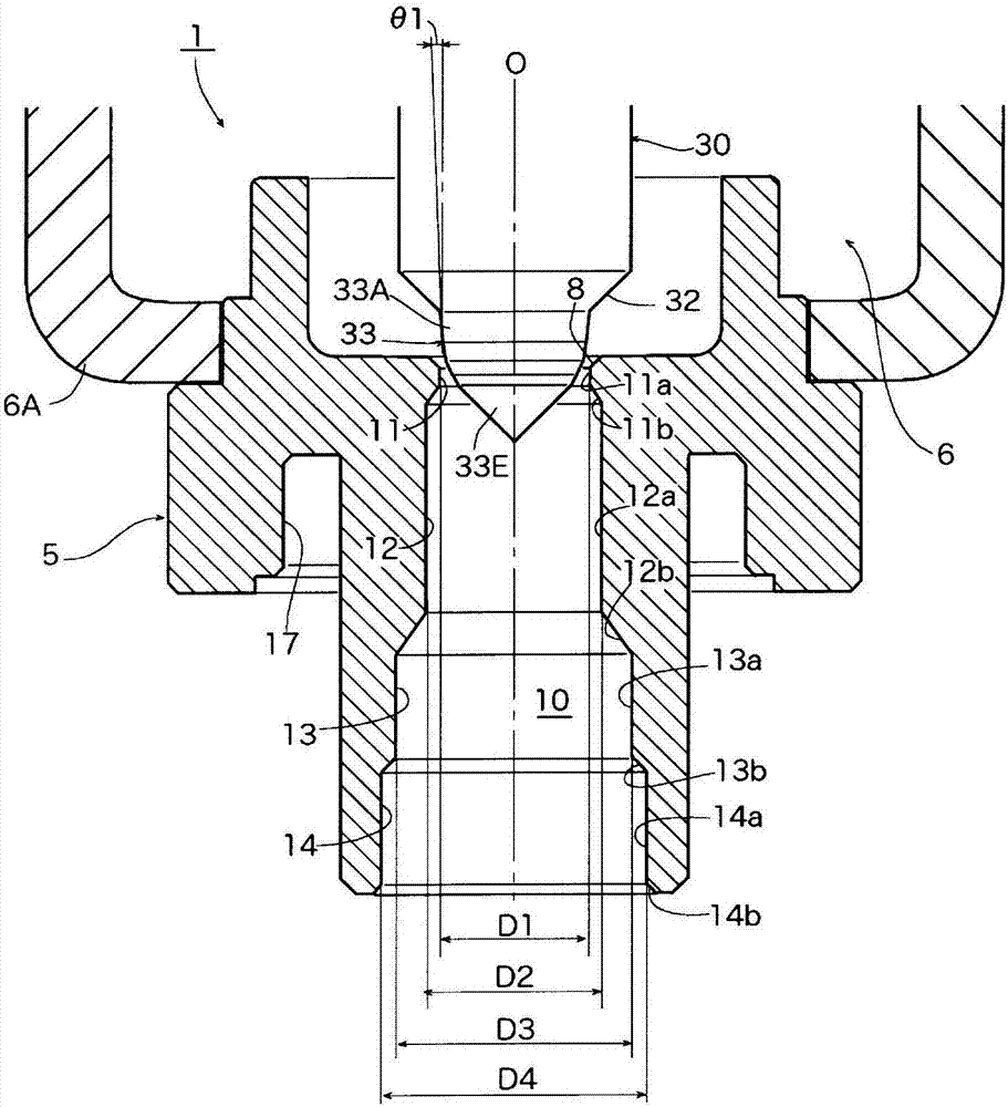
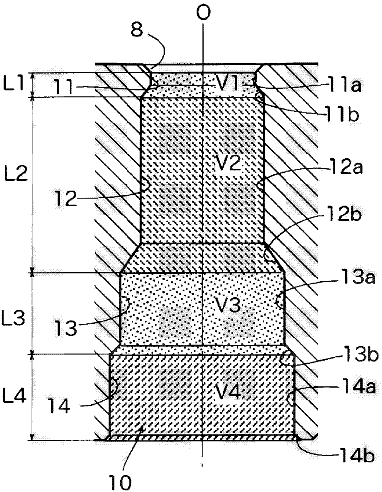
[0036] Figure 1AIt is a cross-sectional view showing an essential part of an embodiment of the flow control valve according to the present invention, Figure 1B is used to describe the composition Figure 1A Diagram of the port length and volume of the 4-stage port portion of the indicated port. In addition, in Figure 1A , Figure 1B , for the above Figure 6A , Figure 6B The parts corresponding to the respective parts of the shown conventional flow regulating valve 3 are given the same reference numerals.

[0037] The flow regulating valve 1 of the illustrated embodiment is the same as the above-mentioned Figure 6A , Figure 6B The conventional flow regulating valve 3 shown is similar to a flow regulating valve used for regulating the flow rate of refrigerant in a heat pump type cooling and heating system, and is formed so as to obtain a characteri...


PUM


Abstract

Provided is a flow control valve that can effectively reduce the generation of noise due to fluctuations in the pressure or a refrigerant separation phenomenon that may occur while a refrigerant passes through the valve orifice, and also reduces the pressure loss and the like. The flow control valve (1) includes a valve body (5) including a valve chamber (6) and a valve orifice (10); and a valve element (30) with a curved surface portion (33) adapted to change the flow rate of a fluid through the valve orifice (10) in accordance with the lift amount of the valve element (30), the curved surface portion (33) having a curvature or a control angle that is increased continuously or in stages toward the tip end of the curved surface portion (33). The orifice diameter of the valve orifice (10) is sequentially increased in four or more stages in a direction away from the valve chamber (6). Further preferably, V2 > V4 > V3 > V1, where the volumes of the first valve orifice portion (11), the second valve orifice portion (12), the third valve orifice portion (13), and the fourth valve orifice portion 14 are V1, V2, V3, and V4, respectively.

Description

technical field [0001] The present invention relates to a flow regulating valve provided with a valve main body provided with a valve chamber and an orifice, and a valve core that changes the flow rate of the fluid flowing through the orifice according to the lift, and particularly relates to a heat pump type valve. A flow regulating valve suitable for regulating the flow of refrigerant in refrigeration and heating systems, etc. Background technique [0002] As the relationship between the valve opening (lift) and the flow rate of the flow regulating valve, that is, the flow characteristic, the linear characteristic and the equal percentage characteristic are well known. The linear characteristic refers to the characteristic that the change rate of the flow rate is constant relative to the change of the valve opening, and the equal percentage characteristic refers to the characteristic that the change rate of the valve opening is proportional to the flow rate. [0003] Fig...

Claims


Application Information

Patent Timeline
Patent Type & Authority Applications(China)
IPC IPC(8): F16K47/02F25B41/06F16K1/38F25B41/20
CPCF16K1/38F16K47/02F25B41/30F16K1/36F16K1/42F16K1/54
Inventor 猪野泰利
Owner FUJIKOKI MFG CO LTD
Why Eureka
Try Eureka