

Determination methods for urban gas pipeline network detection range and detection coverage rate
A technology of detection range and determination method, applied in pipeline systems, gas/liquid distribution and storage, instruments, etc., can solve the problems of inability to accurately judge the detection range of pipeline inspection and low detection efficiency of urban gas pipe network, and avoid detection. The generation of blind spots, reliable technical support, and the effect of avoiding repeated detection
- Summary
- Abstract
- Description
- Claims
- Application Information
AI Technical Summary
Problems solved by technology
Method used
Image

Examples
Embodiment 1
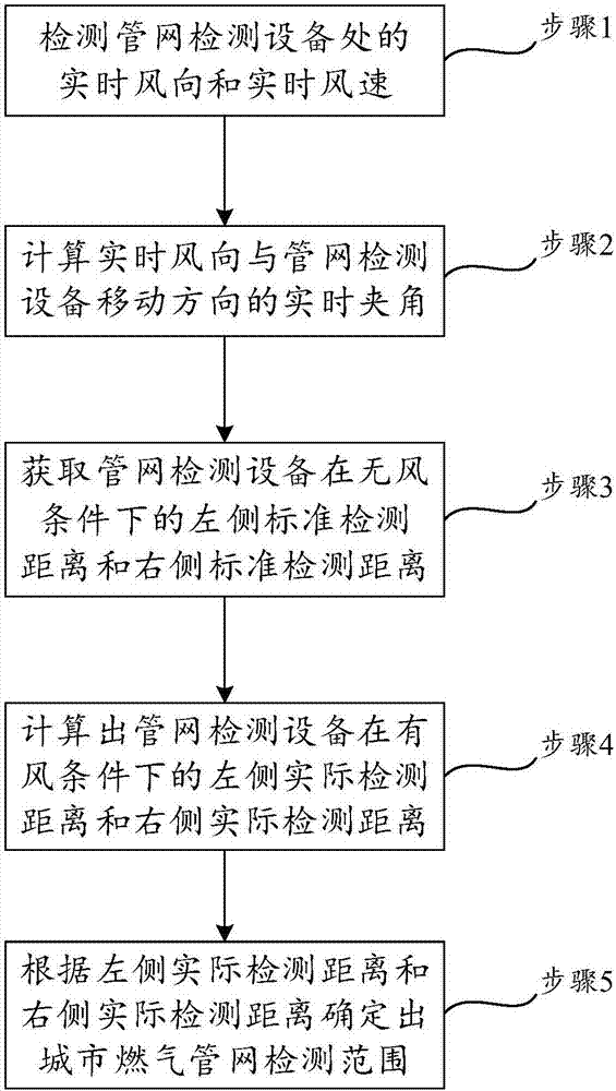
[0041] like figure 1 As shown, the present invention discloses a method for determining the detection range of an urban gas pipeline network, which takes into account the wind direction, wind speed, and driving track factors that affect the detection range of the pipeline network. The determination method specifically includes the following steps.
[0042] Step 1, during the movement of the pipeline network detection equipment, detect the real-time wind direction and real-time wind speed at the pipeline network detection equipment; in this embodiment, the pipeline network detection equipment is preferably a leak detection vehicle.
[0043] Step 2, calculating the real-time included angle between the real-time wind direction and the moving direction of the pipe network detection equipment.
[0044] Step 3, obtain the standard detection distance on the left and the standard detection distance on the right of the pipe network detection equipment under no wind conditions; in this ...
Embodiment 2
[0064] This embodiment is basically the same as the solution disclosed in Embodiment 1. The difference is that in this embodiment, the actual detection distance on the left side and the actual detection distance on the right side of the pipe network detection equipment under windy conditions need to be calculated by means of coordinates. In particular, there is another big difference between this embodiment and the embodiment: the angle between the wind direction and the moving direction of the pipe network detection equipment ranges from 0° to 360°. The specific description is as follows:
PUM
 Abstract
Description
Claims
Application Information